background image

Diagnostic information

2-7


4036-402

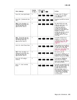
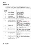
Scan module does not move to the home position

Scan module does not move to the flatbed position

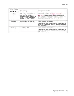
System hangs while booting or displays erratic behavior

Cause

Relevant unit

Check 

Action

Home position sensor—
main scanner card 
connection failure

None

Visual check

Connect the connector.

Home position sensor 
failure

Sensor in the flatbed 
optical unit

Visual check

Replace the flatbed optical unit.

Power supply—main 
scanner card connection 
failure

None

Visual check

Connect the connector.

Power supply fails

Power supply

Test LVPS (+5V, 
+24V, GND)

Replace the power supply.

Lamp failure

Lamp

Visual check

Replace the flatbed lamp.

Inverter failure

Inverter

Visual check

Replace the flatbed lamp inverter.

Flatbed optical unit—
main scanner card 
connection failure

None

Visual check

Connect the connector.

CCD card fails

Flatbed optical unit

Visual check

Replace the flatbed optical unit.

Cause

Relevant unit

Check 

Action

Power supply.—-main 
scanner card connection 
failure

None

Visual check

Connect the connector.

Power supply fails

Power supply

Test LVPS (+5V, 
+24V, GND)

Replace the power supply.

Motor—main scanner 
card connection failure

None

Visual check

Connect the connector.

Motor failure

Carrier motor

Visual check

Replace the flatbed optical unit.

Belt broken or loose

Carrier belt

Visual check

Reposition belt or replace if 
defective.

Cause

Relevant unit

Check 

Action

Corrupt software on hard 
disk drive

Hard disk drive

Visual check

Refresh the hard disk drive 
software. See 

“Hard disk drive 

refresh” on page 3-4

.

Summary of Contents for 16C0365 - 5500 MFP

Page 1: ... 4036 402 Table of Contents Start Diagnostics Safety and Notices Trademarks Index Lexmark and Lexmark with diamond design are trademarks of Lexmark International Inc registered in the United States and or other countries ...

Page 2: ...y time Comments may be addressed to Lexmark International Inc Department D22A 032 2 740 West New Circle Road Lexington Kentucky 40550 U S A or e mail at ServiceInfoAndTraining Lexmark com Lexmark may use or distribute any of the information you supply in any way it believes appropriate without incurring any obligation to you You can purchase additional copies of publications related to this produc...

Page 3: ...nd service checks 2 6 The power does not come on 2 6 Scan module does not move to the lock position 2 6 Scan module does not move to the home position 2 7 Scan module does not move to the flatbed position 2 7 System hangs while booting or displays erratic behavior 2 7 Image does not appear 2 8 Large jitter 2 8 Irregular movement 2 8 Image unclear 2 8 Strange sound generated flatbed 2 9 Frequent pa...

Page 4: ...mp assembly 3 34 Flatbed CCD optical unit 3 36 Multifunction device MFD controller card cage 3 38 Hard disk drive MFD controller card power distribution card memory DIMM and cooling fan 3 41 Main scanner card 3 42 Connector locations 4 1 Locations 4 1 Paper path and sensors 4 1 Internal view 4 2 Connectors 4 3 Main scanner card 4 3 Power distribution card 4 3 Low voltage power supply 4 4 Preventiv...

Page 5: ...gnes d entretien et de réparation de ce produit s adressent uniquement à un personnel de maintenance qualifié Le démontage et l entretien de ce produit pouvant présenter certains risques électriques le personnel d entretien qualifié devra prendre toutes les précautions nécessaires ATTENTION Ce symbole indique la présence d une tension dangereuse dans la partie du produit sur laquelle vous travaill...

Page 6: ...e el mantenimiento de este producto está dirigida exclusivamente al personal cualificado de mantenimiento Existe mayor riesgo de descarga eléctrica y de daños personales durante el desmontaje y la reparación de la máquina El personal cualificado debe ser consciente de este peligro y tomar las precauciones necesarias PRECAUCIÓN este símbolo indica que el voltaje de la parte del equipo con la que es...

Page 7: ...roducte està orientada exclusivament a professionals i no està destinada a ningú que no ho sigui El risc de xoc elèctric i de danys personals pot augmentar durant el procés de desmuntatge i de servei d aquest producte El personal professional ha d estar ne assabentat i prendre les mesures convenients PRECAUCIÓ aquest símbol indica que el voltatge de la part de l equip amb la qual esteu treballant ...

Page 8: ...djustments and removing and installing FRUs 4 Connector locations uses illustrations to identify the connector locations and test points on the product 5 Preventive maintenance contains the lubrication specifications and recommendations to prevent problems 6 Parts catalog contains illustrations and part numbers for individual FRUs Definitions Note A note provides additional information Warning A w...

Page 9: ... Ease of use The user interface on the front of the scanner looks like a panel on a copier with standard phone keys added The operating steps follow the same procedure as that of a copier or fax machine Digital copier and full function fax machine When the scanner is connected to a Lexmark MFP it performs convenient digital copying When connected to a telephone line the scanner performs a full fax...

Page 10: ... install the connectors on the scanner with the power supply turned ON Use care not to drop small parts or screws inside the unit when disassembling and reassembling Do not pull the connector cable when disconnecting it Hold the connector When carrying the scanning head unit put it in an anti static bag Keep the document glass platen surface clean with a dry clean lint free cloth Maintenance tools...

Page 11: ...x Scan method Color charge coupled device CCD Light source Cold cathode fluorescent lamp CCFL Scan area ADF and flatbed Max 297 mm x 432 mm 11 7 x 17 in Display 640 x 480 color VGA touch screen Image types 1 8 24 bit with image processing Scan accuracy Flatbed ADF Leading edge 1 2 mm 2 2 mm Side edge 1 2 mm 2 2 mm Skew 1 mm 2 mm Magnification rate tolerance horizontal and vertical 1 0 1 0 1 5 1 5 ...

Page 12: ...d a user interface with a touch screen panel and a multifunction device controller cage located within the base of the scanner The MFD controller cage includes a MFD controller card to process all jobs performed on the X5500 and communicates with the rest of the scanner a hard disk drive containing the operational code for the system and providing memory for processing jobs and a power distributio...

Page 13: ...ted opposite the pick rollers is used to properly feed the pages one at a time when placed on the input tray The flatbed optical unit carrier is positioned to the far left so when the paper passes through the ADF the bottom of the page is scanned by the flatbed CCD The home position sensor detects when the carrier is in the proper position for ADF scanning In addition an ADF cover open sensor dete...

Page 14: ... Feeder CCD Charge Coupled Device CCFL Cold Cathode Fluorescent Lamp CDB Command Data Blocks DMM Digital Multimeter LED Light Emitting Diode MFD Multifunction Device PCBA Printed Circuit Board Assembly SCSI Small Computer System Interface UI User Interface ...

Page 15: ...rder to perform the task Start This chapter describes two methods to solve the operational problems The first relies on the scanner internal diagnostics to report error codes The second uses troubleshooting techniques to isolate the problem In many cases the internal error codes will help you to locate the source of the problem quickly If no error codes are reported or if the error codes do not lo...

Page 16: ...stem is powered down Use the following tables to read the beep LED codes and follow the recommended repair action There are four pairs of LEDs along the rear edge of the MFD controller card The LEDs are visible from the rear of the scanner though holes in the metal card cage panel The LED patterns in the table below depict which LEDs are visible from the rear of the scanner Error message Number of...

Page 17: ...e Replace or reformat the hard disk drive See Hard disk drive refresh on page 3 4 Error 34 Hard Drive failure 3 There was an error writing to the hard disk drive Replace or reformat the hard disk drive See Hard disk drive refresh on page 3 4 Note Error message not displayed Only beep code and LED patterns are generated for error 51 5 No memory found The memory DIMM was not detected or not function...

Page 18: ...5 3 for information about the locking mechanism Check the flatbed motor belt and home position sensor for proper operation Replace any defective parts If no defective parts are found replace the main scanner card 7 Flatbed Lamp Failure Check the flatbed optical unit for proper connection Replace the flatbed lamp or optical unit if necessary 8 ADF Lamp Failure Check the ADF internal subassembly for...

Page 19: ...ts check the connection of the cable to the flatbed optical unit Replace the optical unit if necessary No beeps SCSI command not supported Scanner communication error Check the 1394 cable connections If the problem remains replace the main scanner card If the persists replace the MFD controller card No beeps Invalid field in CDB Scanner communication error Check the 1394 cable connections If the p...

Page 20: ...stribution card Power distribution card Check the power distribution card 5V GND Replace the failed power distribution card MFD controller card MFD controller card None If problem still exists replace MFD controller card Check explains how to check the failed item To do a visual check observe the part To do a tester check check the voltage levels of the relevant units See Connector locations on pa...

Page 21: ... failure Inverter Visual check Replace the flatbed lamp inverter Flatbed optical unit main scanner card connection failure None Visual check Connect the connector CCD card fails Flatbed optical unit Visual check Replace the flatbed optical unit Cause Relevant unit Check Action Power supply main scanner card connection failure None Visual check Connect the connector Power supply fails Power supply ...

Page 22: ...lure Carrier motor Visual check Replace the flatbed optical unit Loose belt Flatbed optical unit belt Visual check Make sure belt is not worn or improperly installed Replace if necessary Home position sensor main scanner card cable failure Flatbed optical unit cable Visual check Replace the flatbed optical unit cable Home position sensor failure Flatbed optical unit Tester check Replace the flatbe...

Page 23: ...on Paper setting failure Operation error Is the paper correctly set in the paper chute Teach users to properly position the paper Paper failure Operation error Is the specified paper used Use specified paper Pick pad and rollers failure Pick pad and rollers Check the pad and rollers for wear Clean replace the pick pad and rollers ADF unit failure ADF unit Replace the ADF unit Replace the ADF unit ...

Page 24: ...c document feeder and then open the cover 2 Carefully pull out the jam If you cannot remove the jam open the document cover and move the roller lever forward Then carefully pull out the jam 3 Close the document cover 4 Close the automatic document feeder Make sure the cover is closed securely ...

Page 25: ...e task Parts replacement 1 Clean the disassembly and assembly location 2 Turn off the power switch and remove the AC plug from the outlet before disassembly and assembly 3 Follow the disassembly and assembly procedures Never loosen the screws of parts that must not be disassembled These screws have a red coating 4 Store the disassembled parts in a clean place to avoid loss 5 Assemble in the revers...

Page 26: ...the steps to perform the calibration The process must be completed from start to finish for successful calibration 1 Enter the SE menu by pressing 4 1 1 2 Select Scanner Menu from the main SE menu 3 Select Scan Calibration from the Scanner menu 4 Place the special calibration sheet facedown on the glass Make sure the sheet is oriented with the leading edge band to the left as shown Close the docum...

Page 27: ...10 Place the sheet facedown in the ADF Make sure the sheet is oriented with the leading edge band to the left as shown 11 Press Start 12 Repeat steps 10 and 11 13 Remove the sheet If the calibration process was successful the screen on the scanner displays Successful Turn the power off and on If the calibration process failed the screen displays Failure Turn the power off and on Repeat the scanner...

Page 28: ...s 10 15 minutes A message will appear on the screen indicating the refresh is in progress Note Do not turn the power off while the refresh is in progress If the system is powered off during this process the refresh procedure is automatically restarted the next time the device is powered on If Please contact service technician is displayed the hard disk drive may be corrupt and should be replaced T...

Page 29: ...6 402 Removals Charge coupled device CCD card screws Screws for the CCD card in the optical unit are as shown These screws have a red coating indicating they should never be loosened Flatbed CCD Optical Unit ADF CCD Optical Unit ...

Page 30: ...3 6 Service Manual 4036 402 ADF assembly 1 Disconnect the ADF to flatbed cable from the flatbed 2 Remove the two thumb screws that secure the hinges ...

Page 31: ...3 Lift the ADF assembly straight up CAUTION Remove the ADF assembly with the cover in the raised position only to ensure the hinges are not energized Note After installing a new ADF assembly perform the Scanner calibration on page 3 2 ...

Page 32: ...3 8 Service Manual 4036 402 ADF upper cover 1 Open the ADF 2 Remove the two screws 3 LIft the upper cover away from the hinge ...

Page 33: ...Repair information 3 9 4036 402 ADF upper guide 1 Remove the ADF upper cover See ADF upper cover on page 3 8 2 Remove the stop guide screw 3 Rotate the ADF upper guide and pull the upper guide free ...

Page 34: ...Manual 4036 402 ADF lower guide 1 Remove the ADF upper guide See ADF upper guide on page 3 9 2 Remove the paper input tray See Paper input tray on page 3 18 3 Remove the six screws A and B 4 Lift the ADF lower guide ...

Page 35: ...Repair information 3 11 4036 402 5 Pull the page size sensor cable through the opening in the ADF lower guide 6 Disconnect the paper present sensor cable ...

Page 36: ...3 12 Service Manual 4036 402 7 Remove the ground screw and washer 8 Lift off the ADF lower guide ...

Page 37: ... information 3 13 4036 402 ADF drive motor 1 Remove the ADF lower guide See ADF lower guide on page 3 10 2 Disconnect the cable to the ADF drive motor 3 Remove the ground screw and disconnect the ground cable ...

Page 38: ...3 14 Service Manual 4036 402 4 Remove the three screws A securing the ADF drive motor 5 Remove the motor A ...

Page 39: ...rmation 3 15 4036 402 ADF controller card 1 Remove the ADF assembly See ADF assembly on page 3 6 2 Place the ADF unit upside down 3 Remove the two screws A to the controller card access cover 4 Remove the cover A ...

Page 40: ...3 16 Service Manual 4036 402 5 Disconnect the four cables from the controller card 6 Remove the two screws A holding the controller card 7 Remove the card A ...

Page 41: ...Repair information 3 17 4036 402 ADF hinge 1 Remove the ADF assembly and place it upside down See ADF assembly on page 3 6 2 Remove the four screws A holding the hinge plate 3 Lift the hinge A ...

Page 42: ...3 18 Service Manual 4036 402 Paper input tray 1 Fold the supports flat against the paper input tray bottom 2 Remove the screw ...

Page 43: ...Repair information 3 19 4036 402 3 Carefully bend the cover back to access the page size sensor cable 4 Disconnect the page size sensor cable 5 Lift to remove the paper input tray ...

Page 44: ... Charge coupled device CCD card screws on page 3 5 These screws have a red coating indicating they should never be loosened 1 Remove the ADF drive motor See ADF drive motor on page 3 13 2 Turn the ADF unit upside down 3 Remove the four screws from the lower ADF frame plate 4 Remove the ground screw 5 Remove the idler rollers ...

Page 45: ...mation 3 21 4036 402 6 Turn the ADF upright 7 Remove the four screws 8 Disconnect the cables from the ADF lamp shutter motor cable ADF controller to ADF sensor card cable from the sensor card ADF paper size sensor ...

Page 46: ...3 22 Service Manual 4036 402 9 Remove the ground screw and disconnect the ground screw cable 10 Disconnect the ADF CCD optical card subassembly cable and release the cable from the restraining clip ...

Page 47: ...Repair information 3 23 4036 402 11 Lift the internal ADF CCD subassembly Note After installing a new internal ADF CCD subassembly perform the Scanner calibration on page 3 2 ...

Page 48: ...3 24 Service Manual 4036 402 ADF pick pad 1 Press the ADF release button and open the upper cover 2 Squeeze the ends of the pick pad ...

Page 49: ...Repair information 3 25 4036 402 3 Remove the pick pad ...

Page 50: ...3 26 Service Manual 4036 402 ADF pick roller 1 Press the ADF release and open the upper cover 2 Release the clip holding the pick roller ...

Page 51: ...Repair information 3 27 4036 402 3 Remove the pick roller ADF paper present sensor 1 Remove the lower ADF guide See ADF lower guide on page 3 10 2 Press the tabs together to remove the sensor ...

Page 52: ...ervice Manual 4036 402 ADF cover open sensor 1 Remove the ADF lower guide See ADF lower guide on page 3 10 2 Disconnect the cover open sensor cable from the sensor card 3 Remove the cable from the cable clips ...

Page 53: ...Repair information 3 29 4036 402 4 Remove the screw that secures the sensor 5 Lift the sensor from the bracket ...

Page 54: ...er interface 1 Remove the ADF assembly See ADF assembly on page 3 6 2 Place the flatbed on its back 3 Remove the three screws to loosen the user interface from the flatbed 4 Place the flatbed upright and slide the user interface off ...

Page 55: ...Repair information 3 31 4036 402 5 Disconnect the cables 6 Remove the user interface ...

Page 56: ...32 Service Manual 4036 402 Upper housing 1 Remove the user interface See User interface on page 3 30 2 Remove the 3 screws on the front of the housing 3 Remove the five screws from the back of the housing ...

Page 57: ...Repair information 3 33 4036 402 4 Pull forward and upward to unlatch the housing Lift the housing off ...

Page 58: ...al 4036 402 Flatbed lamp assembly Warning Do not touch the lamp or you may damage the scanner 1 Remove the upper housing See Upper housing on page 3 32 2 Remove the two screws 3 Remove the flatbed CCD optical unit cover ...

Page 59: ...6 402 4 Unlatch the lamp assembly from the flatbed CCD optical unit and remove the lamp assembly toward the rear of the flatbed 5 Disconnect the lamp cable from the inverter 6 Remove the lamp assembly from the wire hooks A and B ...

Page 60: ...ice Manual 4036 402 Flatbed CCD optical unit Warning Do not loosen the red coated screws in the CCD optical unit 1 Remove the upper housing See Upper housing on page 3 32 2 Remove the screw 3 Slide the shaft out ...

Page 61: ...Repair information 3 37 4036 402 4 Lift the belt from the hook 5 Disconnect the ribbon cable from the CCD 6 Remove the flatbed CCD optical unit ...

Page 62: ...rs as shown Note After installing a new optical unit perform the Scanner calibration on page 3 2 Multifunction device MFD controller card cage CAUTION Controller cage edges are sharp 1 Remove the ADF assembly See ADF assembly on page 3 6 2 Place the flatbed upside down and remove the eight screws A from the bottom housing ...

Page 63: ...Repair information 3 39 4036 402 3 Slide the card cage to expose the user interface cables 4 Turn the unit around and lift the card cage to disconnect the user interface cables ...

Page 64: ...3 40 Service Manual 4036 402 5 Remove the ground screw 6 Disconnect the two cables from the main scanner card 7 Remove the MFD controller cage ...

Page 65: ...e MFD controller card cage See Multifunction device MFD controller card cage on page 3 38 2 With the MFD controller card cage positioned upside down near the edge of a table remove the two screws A from the backside and the three screws B from the bottom 3 Turn the MFD controller card upright and lift the upper shield from the cage ...

Page 66: ...emove the component you want from within the MFD card cage Main scanner card 1 Remove the MFD controller card cage Multifunction device MFD controller card cage on page 3 38 2 Remove the five cables connected to the main scanner card ...

Page 67: ...ation 3 43 4036 402 3 Remove the seven screws that secure the shield and the main scanner card 4 Remove the main scanner card Note After installing a new main scanner card perform the Scanner calibration on page 3 2 ...

Page 68: ...3 44 Service Manual 4036 402 ...

Page 69: ...Connector locations 4 1 4036 402 4 Connector locations Locations Paper path and sensors ...

Page 70: ...4 2 Service Manual 4036 402 Internal view ...

Page 71: ...cage when measuring the voltage for the main scanner card Main scanner card Power distribution card Main scanner card Pin no Assignment J3 1 5V dc 2 5V dc 3 5V dc 4 5V dc 5 Ground J6 1 5V dc 2 5V dc 3 5V dc 4 5V dc 5 Ground J9 1 5V dc 2 5V dc 3 5V dc 5 5V dc 5 Ground J10 1 5V dc 2 Ground Power distribution card Pin no Assignment J2 1 Ground 2 Ground 3 Ground 4 24V dc 5 5V dc 6 5V dc ...

Page 72: ...d chart represents the power supply output connector Low voltage power supply Pin no Wire color Assignment 1 Black Ground 2 Black Ground 3 Black Ground 4 Black Ground 5 Black Ground 6 Black Ground 7 White 24V dc 8 Red 5V dc 9 Yellow 12V dc 10 Red 5V dc 11 Red 5V dc 12 Red 5V dc ...

Page 73: ...preventative maintenance either every six months or every 60 000 sheets scanning Cleaning Cover and glass With soft cloth wipe the cover and glass If the dirt is heavy use a neutral cleanser or alcohol Wipe the glass carefully so no cleanser remains on the surface Touch screen Wipe the touch screen with a clean lint free cotton cloth dampened with water ...

Page 74: ...5 2 Service Manual 4036 402 ADF unit Press the release button and lift the upper cover Clean the pick pad pick roller and feed rollers with a lint free cloth and isopropyl alcohol ...

Page 75: ...ough people to help you If you need to transport the scanner follow these instructions to relock the scanner Warning Failure to lock the scan mechanism before moving the scanner can cause internal damage 1 Turn the scanner off 2 Open the document cover 3 Turn the scanner on 4 When the scanning mechanism reaches the far left side of the scanner glass quickly turn the scanner off 5 Move the switch t...

Page 76: ...5 4 Service Manual 4036 402 ...

Page 77: ...the same list Common parts are shown by one index number Parts peculiar to one or the other of the assemblies are listed separately and identified by description NS Not Shown in the Asm Index column indicates that the part is procurable but is not pictured in the illustration PP Parts Packet in the Description column indicates the part is contained in a parts packet ...

Page 78: ...6 2 Service Manual 4036 402 Assembly 1 Upper Scanner ...

Page 79: ...otor ADF drive 9 56P2065 1 Sensor assembly ADF paper feed 10 56P2050 1 Cable ADF to flatbed 11 56P2113 1 Base ADF assembly 12 56P2114 1 Hinge ADF assembly right 13 56P2116 1 Card assembly ADF controller 14 56P2051 1 Housing flatbed upper 15 56P2115 1 Hinge ADF assembly left 16 56P2052 1 Panel assembly user interface 17 56P2222 1 Strip MYLAR paper exit 18 56P2064 1 Sensor assembly cover open 19 56P...

Page 80: ...6 4 Service Manual 4036 402 Assembly 2 Lower scanner 12 1 2 3 4 5 6 7 8 9 11 10 13 14 15 16 17 17 ...

Page 81: ...337 1 Power cord Egypt Gulf Ireland United Kingdom 7 11D0338 1 Power cord Israel 7 11D0339 1 Power cord South Africa 7 11D0340 1 Power cord Australia and New Zealand 8 56P0192 1 Card assembly power distribution 9 56P2058 1 Drive assembly hard disk drive 10 56P1808 1 Fan control cage cooling 11 56P2170 1 Cable user interface 7 pin 12 56P2171 1 Cable user interface 14 pin 13 56P2172 1 Cable user int...

Page 82: ...6 6 Service Manual 4036 402 Assembly 3 Miscellaneous Asm index Part number Units Description 3 1 7372358 1 Field replacement kit packaging 2 56P2169 1 Scanner calibration sheet ...

Page 83: ...r open sensor ADF parts catalog 6 3 removal 3 28 covers ADF assembly 3 6 ADF cover release 4 1 5 2 ADF upper parts catalog 6 3 removal 3 8 controller card access cover 3 15 upper housing 3 32 D description 1 1 drive motor ADF parts 6 3 removal 3 13 E error codes CCD lamp flashes 2 4 MFD controller 2 2 F features 1 1 field replacement kit 6 6 flashes lamp 2 4 flatbed lamp assembly parts catalog 6 5...

Page 84: ...unction device MFD controller card cage 3 38 O operator panel see user interface overview 1 1 P packaging 6 6 pad ADF pick removal 3 24 paper input tray parts catalog 6 3 removal 3 18 paper jam clearing 2 10 paper length sensor 4 1 paper present sensor ADF location 4 1 parts catalog 6 3 removal 3 27 parts catalog lower scanner 6 4 miscellaneous 6 6 upper scanner 6 2 parts replacement 3 1 pick pad ...

Page 85: ...ensor 3 21 service checks see symptoms service guidelines 1 2 software update 3 4 specifications scanner 1 3 start diagnostics 2 1 symptoms boot failure 2 7 double feeds 2 9 erratic behavior 2 7 image missing 2 8 image unclear 2 8 irregular movement 2 8 jitter 2 8 paper jams 2 9 power 2 6 scanning 2 6 2 7 skew 2 9 sound ADF 2 9 sound flatbed 2 9 T theory mechanical operation 1 5 system description...

Page 86: ...I 4 Service Manual 4036 402 ...

Page 87: ... disk to controller 6 5 56P1808 Fan control cage cooling 6 5 56P2044 Sub assembly internal ADF CCD 6 3 56P2045 Guide ADF upper 6 3 56P2046 Tray paper input 6 3 56P2047 Guide ADF lower 6 3 56P2048 Cover ADF upper 6 3 56P2049 Kit ADF pick roller and pad 6 3 56P2050 Cable ADF to flatbed 6 3 56P2051 Housing flatbed upper 6 3 56P2052 Panel assembly user interface 6 3 56P2053 Lamp assembly flatbed 6 5 5...

Page 88: ...56P2171 Cable user interface 14 pin 6 5 56P2172 Cable user interface 15 pin 6 5 56P2177 Assembly complete ADF 6 3 56P2222 Strip MYLAR paper exit 6 3 56P2554 Card assembly MFD controller worldwide except Australia and New Zealand 6 5 56P2555 Card assembly MFD controller only Australia or New Zealand 6 5 56P9910 Card assembly 128MB DIMM 6 5 7372358 Field replacement kit packaging 6 6 ...

Reviews: