

DI-000-RZS15-00C
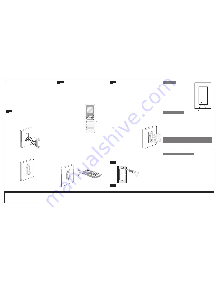
• Position all wires to provide room in outlet wall box for device.
• Ensure that the word “TOP” is facing up on device strap.
• Partially screw in mounting screws in wall box mounting holes.
NOTE:
Dress wires with a bend as shown in diagram in order to
relieve stress when mounting device.
• Restore power at circuit breaker or fuse.
• Press pad until locator light is OFF. Lights should turn ON.
If lights do not turn ON, refer to the TROUBlESHOOTING section.
lIMITED 5 YEAR WARRANTY AND EXClUSIONS
Leviton warrants to the original consumer purchaser and not for the benefit of anyone else that this product at the time of its sale by Leviton is free of defects in materials and workmanship under normal and proper use for five years from the purchase date. Leviton’s only obligation is to correct such defects by repair or replacement,
at its option, if within such five year period the product is returned prepaid, with proof of purchase date, and a description of the problem to
leviton Manufacturing Co., Inc., Att: Quality Assurance Department, 59-25 little Neck Parkway, little Neck, New York 11362-2591.
This warranty excludes and there is disclaimed liability
for labor for removal of this product or reinstallation. This warranty is void if this product is installed improperly or in an improper environment, overloaded, misused, opened, abused, or altered in any manner, or is not used under normal operating conditions or not in accordance with any labels or instructions.
There are no other or
implied warranties of any kind, including merchantability and fitness for a particular purpose
, but if any implied warranty is required by the applicable jurisdiction, the duration of any such implied warranty, including merchantability and fitness for a particular purpose, is limited to five years.
leviton is not liable for incidental,
indirect, special, or consequential damages, including without limitation, damage to, or loss of use of, any equipment, lost sales or profits or delay or failure to perform this warranty obligation
. The remedies provided herein are the exclusive remedies under this warranty, whether based on contract, tort or otherwise.
Testing your Switch prior to mounting in wall
box:
Step 5
Step 6
Including Switch into Z-Wave
TM
Network:
NOTES:
•
If using a non-Leviton Programmer/Controller, refer to the Programmer/
Controller instruction sheet for Including a device.
A)
If using a Leviton Z-Wave
TM
Programmer/Controller, Cat. No. RZCPG,
press the Menu button and scroll down to System Setup. Press the
center button to select System Setup Menu. Press the center button to
select Network.
B)
While standing close to the
switch (approximately 2-5
ft.), press the center button
to <Include> device in the
network.
NOTE:
Only one device may
be included at a time.
DO
NOT
put multiple devices into
the Inclusion mode at any
time.
C)
While the Programmer/
Controller is in the Inclusion
mode and the Locator LED
is ON on the switch, press
the push pad to turn on the
switch. The Programmer/
Controller will verify inclusion
and the Locator LED will turn
OFF.
If the switch is flashing Amber
while in the Inclusion mode,
the Programmer/Controller is still trying to communicate with the switch.
Wait until the device stops flashing, then press the push pad.
NOTE:
If the Locator LED on the switch turns solid Red while including,
there has been a communication error. Refer to Troubleshooting
section.
D)
The Primary Programmer/Controller will assign a node ID number
(Name) for this device.
NOTE:
This ID number (Name) will be stored in the controller to be
used for future reference.
NOTE:
You may name or edit the node of this device at this time.
E)
The switch is now installed in the network
.
NOTE:
If the switch has been successfully Included in the network and the
user tries to Include it again without first excluding it from the network, the
switch will retain the first node ID it had received and ignore the second.
Programmer/Controller
Cat. No. RZCPG
NOTE:
Programmer/Controller must
be in close proximity to switch when
including in the network.
Step 7
Excluding Switch from Z-Wave
TM
Network:
For additional information, contact leviton’s
Techline at 1-800-824-3005 or visit leviton’s
website at www.ViziaRF.com
Protected under U.S. Patent Number 6,388,399 and patents pending and
licensed under U.S. Patents Numbers 5,905,442, and 5,982,103
This equipment has been tested and found to comply with the limits for
a Class B Digital Device, pursuant to Part 15 of the FCC Rules. These
limits are designed to provide reasonable protection against harmful
interference in a residential installation. This equipment generates, uses,
and can radiate radio frequency energy and, if not installed and used in
accordance with the instructions, may cause harmful interference to radio
communications. However, there is no guarantee that interference will
not occur in a particular installation. If this equipment does cause harmful
interference to radio or television reception, which can be determined
by turning the equipment OFF and ON, the user is encouraged to try to
correct the interference by one or more of the following measures:
• Reorient or relocate the receiving Antenna.
• Increase the separation between the equipment and the receiver.
• Connect the equipment into an outlet on a circuit different from that to
which the receiver is connected.
• Consult the dealer or an experienced radio/tv technician for help.
FCC COMPlIANCE
STATEMENT
Push
Pad
locator
light
NOTE:
The locator light will illuminate when
the load is in the OFF position to facilitate
access in the dark.
Push Pad (Default settings)
Turn ON from OFF position:
Tap – Lights turn ON.
Turn OFF from ON position:
Tap – Lights turn OFF.
If there is a power outage, when the power
is restored, the lights will return to the last
setting before the power interruption.
Cleaning:
Clean with a damp cloth.
DO
NOT
use chemical cleaners.
OPERATION
TROUBlESHOOTING
• lights Flickering
- Lamp has a bad connection.
- Wires not secured firmly under terminal screws of switch
and/or remote.
• light does not turn ON and locator lED does not turn ON
- Circuit breaker or fuse has tripped.
- Lamp is burned out.
- Lamp Neutral connection is not wired.
• Remote does not operate lights
- Ensure that total wire length does not exceed 300 ft (90 m).
Restore Power:
Restore power at circuit breaker or fuse.
Installation is complete.
Step 9
Switch Mounting:
TURN OFF POWER AT CIRCUIT BREAKER OR FUSE.
Step 8
Installation may now be
completed by tightening
mounting screws into wall
box. Attach wallplate.
NOTE:
It is very important to accurately Exclude devices from the network
when moving or removing a device from a Z-Wave
TM
network. This ensures
that all information has been removed from your Primary Programmer/
Controller's information table and is not counted on to be part of the mesh
network.
A)
If using a Leviton Z-Wave
TM
Programmer/Controller, Cat. No. RZCPG,
press the Menu button and scroll down to System Setup. Press the
center button to select System Setup Menu. Press the center button to
select Network.
B)
While standing close to the switch (approximately 2-5 ft.), press the
center button to <Exclude> device from the network.
C)
While the Programmer/Controller is in the Exclusion mode and the
locator LED is ON on the Dimmer, press the push pad to turn on the
switch. The Programmer/Controller will verify Exclusion and the locator
LED will turn OFF.
If the switch is flashing Amber while in the Exclusion mode, the
Programmer/Controller is still trying to communicate with the switch. Wait
until the device stops flashing, then press the push pad.
Factory Default:
If your switch is not responding, or you are unable to control it after you
have tried to Include/Exclude it multiple times, it may be necessary to reset
the switch to its original factory settings. To
accomplish this, proceed as follows:
• On the switch, engage the air-gap switch
by gently pulling the bottom of the push pad
until it lifts completely out of the frame and
a click is heard.
(refer to figure)
. Wait 5
seconds and then press the push pad back
into the frame and hold push pad until the
locator LED flashes Amber and turns solid
Red. The switch is now reset. Once the
switch is reset, it will be necessary to Re-
Include it to a network before it can be used.
CAUTION:
SETTING A DEVICE TO A
FACTORY DEFAULT DOES NOT EXCLUDE
THAT DEVICE FROM A NETWORK. THE
EXCLUSION PROCEDURE MUST STILL BE
FOLLOWED TO REMOVE THE DEVICE FROM
THE PRIMARY CONTROLLER’S INFORMATION TABLE. FAILURE TO DO
SO MAY RESULT IN SYSTEM THAT IS SLOW TO RESPOND, OR MAY
FAIL TO RESPOND TO SOME DEVICES.
Gently lift bottom of
push pad out
1
ON
2
ON
3
ON
4
ON
OFF
OFF
OFF
OFF
Programmer/Controller
Cat. No. RZCPG
Menu Button
Center Button
WIRING COORDINATING REMOTE:
Connect wires per WIRING DIAGRAM as follows:
NOTE:
"BK" and "RD" terminals on coordinating remote are unused.
Tighten both screws.
NOTE:
Maximum wire length from switch to last remote is
300 ft (90 m).
• Green or bare copper wire in wall box to Green terminal screw.
• Load wall box wire identified (tagged) when removing old switch to
First Traveler
(note color as above)
.
• Second Traveler wall box wire
(note color as above)
to terminal
screw marked "YL/RD". This traveler from the remote must go to the
terminal screw on the switch marked "YL/RD".
• Remove White insulating label from terminal screw marked "WH".
• Line Neutral wall box wire to terminal screw marked "WH".
• Proceed to Step 5.


