


FIGURE 9 - RESETTING CONTROLLER OUTPUTS
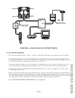
OUTPUT APPLICATIONS
GENERAL PURPOSE SWITCHING APPLICATIONS
This output will supply 12 VDC to the output terminal when its corresponding unit is ON. Output 1 is designated Unit 65 through
2XWSXWZKLFKLV8QLW7KLVFDQEHXVHGWRGULYHUHOD\VIRUPDQ\GLIIHUHQWDSSOLFDWLRQVLQFOXGLQJVZLWFKLQJVSULQNOHUYDOYHVDQG
low-voltage lighting.
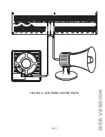
SOUNDER TRIGGERING
7KLVRXWSXWFDQEHXVHGDVDWULJJHUIRUVLUHQDQGYRLFHGULYHUV:KHQDGULYHUUHTXLUHVDVHSDUDWHLQSXWIRUEXUJODU\DQG¿UH\RXFDQ
FRQ¿JXUHWKLVRXWSXWWRJLYHDYROWDJHWULJJHUWRWKHGULYHU$OVRHDFKDUHDFDQKDYHLWVRZQVRXQGHU
Page 16
CONTROLLER OUTPUTS
The
Omni
,,HSURYLGHVSURJUDPPDEOHKDUGZLUHGYROWDJHRXWSXWVDQGWZRKRUQYROWDJHRXWSXWV7KHVHRXWSXWVDUH
SURJUDPPDEOHIRUWKHIROORZLQJRXWSXWW\SHV
%
General Purpose low voltage switching applications (12 VDC) - Units 65 - 72
%
Sounder triggering (a trigger for siren and voice drivers for BURG and FIRE)
%
Communicator outputs (radio, cellular, or any other type of auxiliary communicator)
%
‘ARMED’ and ‘OK TO ARM’ outputs
%
Switched Output (to power smoke detectors and cycle power to latching devices)
Outputs 1 - 8
can supply a
maximum
of 100 mA each. These outputs are included in the total DEVICES load, which cannot
exceed 1A.
,IWKH,QWHULRURU([WHULRU6RXQGHULVFRQ¿JXUHGWRDQ2XWSXW7\SHWKH+251RXWSXWVFDQVXSSO\D
maximum
of 1A.
HORN outputs are included in the total HORNS load, which can not exceed 1A.
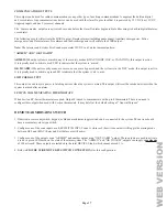
RESET OUTPUTS
Outputs 1-8 are protected from an overload condition. If an overload condition occurs on an output, it will shut off (the output will
supply 0V). When this occurs, the “Output Fault” (D26) LED (marked “A” if Figure 8) will illuminate. To reset the output, remove
the device causing the overload condition, then press the “Reset Outputs” (S1) Switch (marked “B” if Figure 9).
A
B
WEB
VERSION


