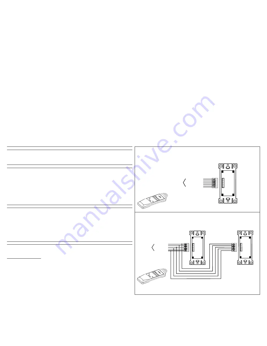
GND (Green)
GND
Not Used
Not Used
+24V DC (Green/White)
+24V DC
CAN-L (Blue/White)
CAN-L
CAN-H (Blue)
CAN-H
LCnet
Back of Scene Controller
GND (Green)
GND
Not Used
Not Used
+24V DC (Green/White)
+24V DC
CAN-L (Blue/White)
CAN-L
CAN-H (Blue)
CAN-H
GND (Green)
GND
Not Used
Not Used
+24V DC (Green/White)
+24V DC
CAN-L (Blue/White)
CAN-L
CAN-H (Blue)
CAN-H
LCnet
Back of Scene Controller
Back of Scene Controller
Wiring Diagram 2 - Two Location Application
Wiring Diagram 1 - Single Station Application
DI-000-NE505-00A
MAX
OFF
SCEN
ES
5
1
2
3
4
6
7
8
MAX
OFF
SCEN
ES
5
1
2
3
4
6
7
8
NE210 Remote
NE210 Remote
TO OPERATE
Scenes 1-4, 5-8,...Scene 29-32 (refer to Step 3 of Scene Programming section):
SCENE BUTTON:
Press the Scene button. The lights will fade ON to the preset light level.
OFF:
Press the OFF button. The lights will fade OFF.
NOTE: Each button will illuminate when pressed except when the Controller is in the Program Mode.
SCENE PROGRAMMING
1. Press and hold button 1 and 3 on the Controller for approximately 5-7 seconds. All the LED’s will blink to indicate that the Controller is in
Program Mode.
NOTE: Pressing any button while the LED’s are flashing in the Program Mode, will exit the mode without any programming stored.
2. Call Scene from Cat. No. D3206/8 (refer to D3206/8 User Guide) or other source.
3. Once the Scene is called, the LED’s will stop flashing and the device will exit Program Mode. The buttons are now programmed based
on the Scene called as follows:
If Scenes 1-4 are called on a LCnet Scene Capable Dimmer, button 1 on the Controller is programmed for Scene 1; button 2 is Scene 2;
button 3 is Scene 3; button 4 is Scene 4.
If Scenes 5-8 are called on a LCnet Scene Capable Dimmer, button 1 on the Controller is programmed for Scene 5; button 2 is Scene 6;
button 3 is Scene 7; button 4 is Scene 8 and so on.
4. The OFF button will always be programmed as OFF.
NOTE: If there is partitioning in the application, repeat the above procedure for each configuration used.
IR PROGRAMMING
The NE505 has a Learning IR capability that allows users to select any button (command from IR Remote) to correspond with desired
scene programmed and OFF.
1. Press and hold the desired Scene or OFF button on the Controller for approximately 5-7 seconds until it’s LED begins flashing. The
Controller is now in the Infrared Remote Control Program Mode.
2. Press the desired button on the IR remote to correspond with the desired Controller button.
NOTE: If Remote generates only one control signal when the button is pressed and the Controller LED continues to flash, you must
press the button on the IR Remote again until the flashing stops.
3. The Controller Scene button is now programmed to respond to the IR command.
4. Repeat the above procedure for each button used, including OFF.
NOTE: If in different configurations the button on the IR Remote calls a different Scene number, you must repeat the programming
procedure.
TROUBLESHOOTING
• If NO LED’s are lit; there is no power
- Check wiring.
• Communication LED does NOT light when the button is pressed
- Check power wiring connections.
For Multiple Power Packs on the Bus:
• The Controller has power (at least the OFF LED is ON) but pressing the buttons have no effect on the lights; there is no communication
between the Controller and the Power Pack
- If the communication LED does NOT flash when a button is pressed, see above.
- If the communication LED does flash, check the address of the Power Pack and Controller (refer to Dimming Power Pack
Instructions).
DI-000-NE505-00A
2/28/02, 1:42 PM
2


