13
INSTALLATION • INSTALLING SCENE CONTROLLER
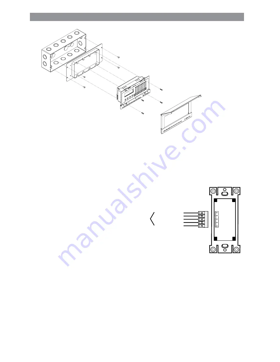
5. Carefully position all wires to provide room in switch box for Multizone Controller. Mount Multizone
Controller to raised cover using the screws provided. See Figure 2-8.
6. Snap faceplate back on. MULTIZONE CONTROLLER INSTALLATION IS COMPLETE.
Installing the NE505 Scene Controller
CAUTION: The Scene Controller operates
off of low voltage (24VDC).
Consult local building codes and
regulations for proper low-voltage
installation.
Installation Instructions
1. If you would like to change the color of the
Controller and need instructions, see Page 16;
otherwise proceed.
2. Connect per wiring diagram (Figure 2-9) as
follows: Insert each lead into appropriate plug
connector location by pushing firmly. If using
stranded wire, twist strands of each lead tightly (making sure that
there are no stray strands) and push firmly into appropriate plug
connector location. Tighten the screws on the plug connector making
sure that no bare conductor shows. Connect plug connector to jack
on the back
of the Controller.
3. Carefully position all wires to provide room in
outlet box for Controller. Mount Controller into
box with mounting screws supplied. NE505 INSTALLATION IS COMPLETE.
GND (Green)
GND
Not Used
Not Used
+24V DC (Green/White)
+24V DC
CAN-L (Blue/White)
CAN-L
CAN-H (Blue)
CAN-H
To LCnet
Figure 2-8:
Mounting Illustration
Figure 2-9:
NE505/NE100 Wiring Diagram


