background image

i

Compliances and Safety Warnings

FCC - Class A

This equipment generates, uses, and can radiate radio frequency energy and, if not 
installed and used in accordance with the instruction manual, may cause interference to 
radio communications. It has been tested and found to comply with the limits for a Class A 
computing device pursuant to Subpart B of Part 15 of FCC Rules, which are designed to 
provide reasonable protection against such interference when operated in a commercial 
environment. Operation of this equipment in a residential area is likely to cause 
interference, in which case the user, at his own expense, will be required to take whatever 
measures may be required to correct the interference. You are cautioned that changes or 
modifications not expressly approved by the party responsible for compliance could void 
your authority to operate the equipment.

You may use unshielded twisted-pair (UTP) for RJ-45 connections - Category 3 or better 
for 10 Mbps connections, Category 5 or better for 100 Mbps connections, Category 5, 5e, 
or 6 for 1000 Mbps connections. For fiber optic connections, you may use 50/125 or 62.5/
125 micron multimode fiber or 9/125 micron single-mode fiber. 

Summary of Contents for GSW-2692

Page 1: ...LevelOne GSW 2692 24 Port 10 100M 2G Combo L2 Stackable Switch Installation Guide Version 1 0 0608...

Page 2: ......

Page 3: ...Operation of this equipment in a residential area is likely to cause interference in which case the user at his own expense will be required to take whatever measures may be required to correct the in...

Page 4: ...e supply system according to EN 61000 3 3 1995 Immunity Product family standard according to EN 55024 1998 Electrostatic Discharge according to EN 61000 4 2 1995 Contact Discharge 4 kV Air Discharge 8...

Page 5: ...LV Safety Extra Low Voltage conditions according to IEC 60950 The conditions are only maintained if the equipment to which it is connected also operates under SELV conditions France and Peru only This...

Page 6: ...15P 15 A 125 V or NEMA 6 15P 15 A 250 V configuration Denmark The supply plug must comply with Section 107 2 D1 Standard DK2 1a or DK2 5a Switzerland The supply plug must comply with SEV ASE 1011 U K...

Page 7: ...y serviceable user parts Warning Installation and removal of the unit must be carried out by qualified personnel only Warning When connecting this device to a power outlet connect the field ground lea...

Page 8: ...a working knowledge of network management You should be familiar with switching and networking concepts Related Publications The following publication gives specific information on how to operate and...

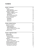
Page 9: ...ntroduction to Switching 2 1 Application Examples 2 2 Collapsed Backbone 2 2 Network Aggregation Plan 2 3 Remote Connections with Fiber Cable 2 4 Making VLAN Connections 2 5 Application Notes 2 6 Chap...

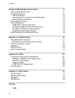
Page 10: ...Ethernet Collision Domain 4 6 Cable Labeling and Connection Records 4 6 Appendix A Troubleshooting A 1 Diagnosing Switch Indicators A 1 Diagnosing Power Problems with the LEDs A 1 Power and Cooling P...

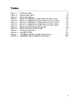
Page 11: ...net Cable Lengths 4 5 Table 4 3 Maximum 1000BASE LX Gigabit Ethernet Cable Length 4 6 Table 4 4 Maximum 1000BASE ZX Gigabit Ethernet Cable Length 4 6 Table 4 5 Maximum Fast Ethernet Cable Length 4 6 T...

Page 12: ...gure 3 2 Attaching the Brackets 3 3 Figure 3 3 Installing the Switch in a Rack 3 4 Figure 3 4 Attaching the Adhesive Feet 3 5 Figure 3 5 Installing an SFP Transceiver into a slot 3 6 Figure 3 6 Connec...

Page 13: ...werful features for Layer 2 switching delivering reliability and consistent performance for your network traffic It brings order to poorly performing networks by segregating them into separate broadca...

Page 14: ...he console port The switch includes a built in network management agent that allows it to be managed in band using SNMP or RMON Groups 1 2 3 9 protocols It also has an RS 232 serial port DB 9 connecto...

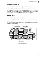
Page 15: ...ther switches or hubs See 1000BASE T Pin Assignments on page B 3 Stacking Ports The unit provides two stacking ports that provide a 4 Gbps stack backplane connection Up to eight switches can be connec...

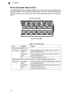
Page 16: ...ber Port has established a valid 10 Mbps network connection Flashing indicates activity On Flashing Green Port has established a valid 100 Mbps network connection Flashing indicates activity Off There...

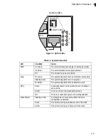
Page 17: ...tem diagnostic test is in progress On Amber The system diagnostic test has detected a fault RPU Green A redundant power unit is attached and is in backup or active mode Amber There is a fault in the r...

Page 18: ...d 10 100 or 1000 Mbps and the communication mode half or full duplex if this feature is supported by the attached device otherwise the port can be configured manually 100BASE TX and 1000BASE T RJ 45 p...

Page 19: ...h of up to 12 8 Gbps Switching table with a total of 8K MAC address entries Provides store and forward switching Wire speed filtering and forwarding Supports flow control using back pressure for half...

Page 20: ...Introduction 1 8 1...

Page 21: ...ice experiencing congestion server power user or hub can be attached directly to a switched port And by using full duplex mode the bandwidth of the dedicated segment can be doubled to maximize through...

Page 22: ...to workstations or servers When the time comes for further expansion just connect to another hub or switch using one of the Fast Ethernet or Gigabit Ethernet ports In the figure below the switch is o...

Page 23: ...the switch are providing 100 Mbps connectivity for up to 24 segments In addition the switch is also connecting several servers at 1000 Mbps Figure 2 2 Network Aggregation Plan Server Farm 10 100 Mbps...

Page 24: ...gments with fiber cable Figure 2 3 Remote Connections with Fiber Cable Headquarters 1000BASE LX SMF 10 kilometers Remote Switch 10 100 Mbps Segments 70 kilometers Remote SwitchC Server Farm Slave Stac...

Page 25: ...ongs Untagged VLANs can be used for small networks attached to a single switch However tagged VLANs should be used for larger networks and all the VLANs assigned to the inter switch links Figure 2 4 M...

Page 26: ...s it is actually required to solve a problem Otherwise back pressure jamming signals may degrade overall performance for the segment attached to the hub 3 As a general rule the length of fiber optic c...

Page 27: ...at the unit is connected to a separate grounded power outlet that provides 100 to 240 VAC 50 to 60 Hz is within 2 m 6 6 feet of each device and is powered from an independent circuit breaker As with a...

Page 28: ...equipment Package Contents GSW 2692 Four adhesive foot pads Bracket Mounting Kit containing two brackets and eight screws for attaching the brackets to the switch Power Cord RS 232 console cable CD Ma...

Page 29: ...the specified operating temperature range See page C 1 Mechanical Loading Do not place any equipment on top of a rack mounted unit Circuit Overloading Be sure that the supply circuit to the rack asse...

Page 30: ...ling a single switch only turn to Connecting to a Power Source at the end of this chapter 4 If installing multiple switches mount them in the rack one below the other in any order 5 If also installing...

Page 31: ...proper air flow 3 If installing a single switch only go to Connecting to a Power Source at the end of this chapter 4 If installing multiple switches attach four adhesive feet to each one Place each de...

Page 32: ...work cable before removing a transceiver Note SFP transceivers are not provided in the switch package Connecting Switches in a Stack Figure 3 6 shows how the stack cables are connected between switche...

Page 33: ...its 5 Optional To form a wrap around topology plug one end of a stack cable into the Down port on the bottom unit and the other end into the Up port on the top unit Figure 3 6 Connecting Switches in a...

Page 34: ...ered on to be sure the PWR LED is lit If not check that the power cable is correctly plugged in 4 If you have purchased a Redundant Power Unit connect it to the switch and to an AC power source now fo...

Page 35: ...Default Baud rate 9 600 bps Character Size 8 Characters Parity None Stop bit One Data bits 8 Table 3 1 Serial Cable Wiring Switch s 9 Pin Serial Port Null Modem PC s 9 Pin DTE Port 2 RXD receive data...

Page 36: ...Installing the Switch 3 10 3...

Page 37: ...both ends Use Category 5 5e or 6 cable for 1000BASE T connections Category 5 or better for 100BASE TX connections and Category 3 or better for 10BASE T connections Cabling Guidelines The RJ 45 ports...

Page 38: ...a hub unless it is actually required to solve a problem Otherwise back pressure jamming signals may degrade overall performance for the segment attached to the hub 3 As each connection is made the Lin...

Page 39: ...eling and Connection Records on page 4 6 Figure 4 2 Network Wiring Connections Equipment Rack side view Switch Patch Panel Punch Down Block Wall Slave Stack Master Uplink Uplink PWR Diag RPU 1 2 3 4 5...

Page 40: ...ease make sure that it can function at a temperature that is not less than the recommended maximum operational temperature of the product You must also use an approved Laser Class 1 SFP transceiver 1...

Page 41: ...ed for 100BASE TX connections should also work for 1000BASE T providing that all four wire pairs are connected However it is recommended that for all critical connections or any new cable installation...

Page 42: ...ch it is connected Note the length of each cable and the maximum cable length supported by the switch ports For ease of understanding use a location based key when assigning prefixes to your cable lab...

Page 43: ...and Connection Records 4 7 4 Differentiate between racks by naming accordingly Label each separate piece of equipment Display a copy of your equipment map including keys to all abbreviations at each...

Page 44: ...Making Network Connections 4 8 4...

Page 45: ...process to complete If flashing continues check that the Master Select button is pressed in on only one switch Check that all stacking cables are properly connected Link LED is Off Verify that the sw...

Page 46: ...igure the switch with a valid IP address subnet mask and default gateway If you have trouble establishing a link to the management agent check to see if you have a valid network connection Then verify...

Page 47: ...the RJ 45 connector are numbered Be sure to hold the connectors in the same orientation when attaching the wires to the pins Figure B 1 RJ 45 Connector Pin Numbers 10BASE T 100BASE TX Pin Assignments...

Page 48: ...led with an X MDI a crossover must be implemented in the wiring When auto negotiation is enabled for any RJ 45 port on this switch you can use either straight through or crossover cable to connect to...

Page 49: ...twisted pair connection does not exceed 100 meters 328 feet Table B 2 1000BASE T MDI and MDI X Port Pinouts Pin MDI Signal Name MDI X Signal Name 1 Bi directional Data One Plus BI_D1 Bi directional D...

Page 50: ...ion does not meet one of the test parameters for 1000BASE T there are basically three measures that can be applied to try and correct the problem 1 Replace any Category 5 patch cables with high perfor...

Page 51: ...Ports 25 28 RJ 45 connector auto MDI X 10BASE T RJ 45 100 ohm UTP cable Category 3 or better 100BASE TX RJ 45 100 ohm UTP cable Category 5 or better 1000BASE T RJ 45 100 ohm UTP or STP cable Category...

Page 52: ...y Power Consumption 25 Watts maximum Maximum Current 1 5 A 100 VAC 0 6 A 240 VAC Switch Features Forwarding Mode Store and forward Throughput Wire speed Flow Control Full Duplex IEEE 802 3x Half Duple...

Page 53: ...net Full duplex flow control Link Aggregation Control Protocol IEEE 802 1D Spanning Tree Protocol IEEE 802 1w Rapid Spanning Tree Protocol ISO IEC 8802 3 Compliances Emissions EN55022 CISPR 22 Class A...

Page 54: ...Specifications C 4 C...

Page 55: ...strands of 50 125 or 62 5 125 micron core fiber cable 1000BASE T IEEE 802 3ab specification for Gigabit Ethernet over 100 ohm Category 5 5e or 6 twisted pair cable using all four wire pairs Auto Negot...

Page 56: ...Fast Ethernet A 100 Mbps network communication system based on Ethernet and the CSMA CD access method Full Duplex Transmission method that allows two network devices to transmit and receive concurrent...

Page 57: ...governs access to the transmission medium facilitating the exchange of data between network nodes MIB An acronym for Management Information Base It is a set of database objects that contains informati...

Page 58: ...as the primary transport protocol and IP as the network layer protocol UTP Unshielded twisted pair cable Virtual LAN VLAN A Virtual LAN is a collection of network nodes that share the same collision...

Page 59: ...gths 4 5 cleaning fiber terminators 4 4 compliances EMC C 3 connectivity rules 10 Mbps 4 6 100 Mbps 4 6 1000 Mbps 4 5 console port pin assignments 3 8 contents of package 3 2 cooling problems A 2 cord...

Page 60: ...rts connecting to 4 1 4 4 power connecting to 3 8 problems troubleshooting A 1 R rack mounting 3 3 rear panel of switch 1 1 rear panel receptacles 1 6 RJ 45 port connections 4 1 pinouts B 3 RMON 1 2 R...

Page 61: ...Index Index 3 tagging 2 5 W web based management 1 2...

Page 62: ...Index Index 4...

Page 63: ......

Page 64: ...GSW 2692 E072006 JC R01...

Reviews: