background image

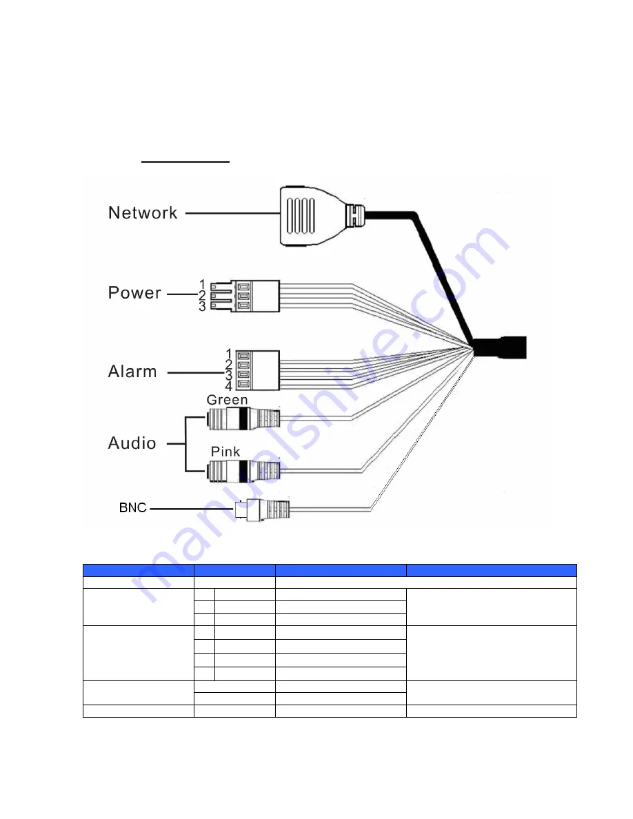
1.4  Connectors 


The Camera is equipped with an all-in-one cable for quick wiring. Definition 

for each connector are as follows. 


All-in-one Cable


Cable


Pin No.


Definition


Remarks


Network (with POE)


RJ-45 connector with LED 


Power


AC 24V-1 


Power connection 

GND 

GND 

AC 24V-2 


Alarm


ALM_DI

- 

Input

- 


Alarm connection 

ALM_DI

+ 

Input

+ 

ALM_DO

- 

Output

- 

ALM_DO

+ 

Output

+ 


Audio I/O


Pink 

Line In/ Mic In 


Two-way audio transmission 

Green 

Line Out 

BNC


Analog video output 


Summary of Contents for FCS-5061

Page 1: ...FCS 5061 Day Night 5 Megapixel PoE Plus Outdoor Network Camera User Manual Ver1 0...

Page 2: ...4 5 1 Using Recording Software 18 5 2 Installing DC Viewer Software Online 19 6 Configuration Operation 21 6 1 Browser based Viewer Introduction 21 6 2 Home Page 23 6 3 System Related Settings 25 6 3...

Page 3: ...75 6 4 1 Video Resolution and Rotate Type 76 6 4 2 Video Compression 78 6 4 3 Video ROI 79 6 4 4 Video OCX Protocol 81 6 4 5 Video Frame Rate 82 6 4 6 Video Mask 83 6 4 7 Audio Audio Mode and Bit Rate...

Page 4: ...Default ID Password Login ID Password root...

Page 5: ...gy the camera is able to filter the intense backlight surrounding a subject and remove noises from video signal The result is that an extremely clear and exquisite picture quality can be produced even...

Page 6: ...wing items listed below FCS 5061 POI 3002 PoE Plus Injector Camera Sunshield Camera Bracket Desiccant Pack Power Terminal Block Alarm Terminal Block M4 Inner Hex Wrench Plastic Screw Anchors x 5 M4 Se...

Page 7: ...1 3 Dimensions The IP Camera s dimensions are shown below...

Page 8: ...ll in one Cable Cable Pin No Definition Remarks Network with POE RJ 45 connector with LED Power 1 AC 24V 1 Power connection 2 GND GND 3 AC 24V 2 Alarm 1 ALM_DI Input Alarm connection 2 ALM_DI Input 3...

Page 9: ...Unscrew two screws on the Sun Shield to remove it NOTE Please note that the Sun Shield is optional Step 2 Unscrew the screw on the Camera Housing and remove the Front Housing NOTE Before installing p...

Page 10: ...ower To power up the IP Camera please plug the AC 24V cable into the Camera s power terminal block Alternatively connect the Ethernet cable to the camera s PoE port and plug the other end of the cable...

Page 11: ...cases you may need use an Ethernet crossover cable when connecting the IP Camera directly to the PC Check the status of the link indicator and activity indicator LEDs if the LEDs are unlit please chec...

Page 12: ...era Follow the steps below to install the IP Camera Step 1 Unpack the IR Bullet IP Camera package and take out the IP Camera Step 2 Connect the power Ethernet alarm audio wires from ceiling or wall to...

Page 13: ...w Items System Requirement Personal Computer 1 Intel R Pentium R M 2 16 GHz or Intel R CoreTM 2 Duo 2 0 GHz 2 2 GB RAM or more Operating System Windows VISTA Windows XP Windows 7 Web Browser Microsoft...

Page 14: ...ceSearch exe which can be found in DeviceSearch folder in the supplied CD Device Search Software Setup Step 1 Double click on the program Device Search exe see the icon below its window will appear as...

Page 15: ...own in the figure below The IP Camera s default IP address is 192 168 0 250 Step 4 Double click or right click and select Browse to access the camera directly via web browser Step 5 Then the prompt wi...

Page 16: ...Refer to the following section for changing the IP Camera s network property Example of Changing IP Camera s Network Property Users can directly change an IP Camera s network property ex from static...

Page 17: ...Note of setting change Wait for one minute to re search the IP Camera Step 4 Click the Device Search button to re search all the devices Then select the IP Camera with the correct MAC address Double...

Page 18: ...eous monitoring and video recording for multiple Network Cameras Please install the recording software then launch the program to add the Network Camera to the Channel list For detailed information ab...

Page 19: ...ity Settings to continue the process The Information Bar just below the URL bar may come out and ask for permission to install the ActiveX Control for displaying video in browser see the figure below...

Page 20: ...20 Once login to the IP Camera users will see the Home page as shown below...

Page 21: ...t System for video playback and recording In this chapter information about main page introduction system related settings and camera settings will be described in detail 6 1 Browser based Viewer Intr...

Page 22: ...related settings etc Streaming setting The administrator can modify video resolution and rotate type and select audio compression mode in this page Camera setting Users can adjust various camera param...

Page 23: ...on the camera model Multiple Languages Support Multiple languages are support for the viewer window interface Screen Size Adjustment Image display size can be adjusted to x1 2 and full screen Talk but...

Page 24: ...n for further details NOTE For users with Windows 7 operating system it is required to log on as an Administrator to implement the Snapshot function Video Streaming Pause Restart button pause restart...

Page 25: ...ity Network DDNS Mail FTP HTTP Application Motion Detection Network Failure Detection Tampering Storage Management Recording File Location View Information Factory Default Software Version Software Up...

Page 26: ...arm message by Mail FTP the host name entered here will display in the alarm message The maximum length of the Host Name is 30 characters Time Zone Select the time zone you are in from the drop down m...

Page 27: ...Sync with NTP Server Network Time Protocol NTP is an alternate way to synchronize your camera s clock with a NTP server Please specify the server you wish to synchronize in the enter field Then select...

Page 28: ...ing on Save the web browser will ask the Administrator for the new password for accessing The maximum length of the password is 14 characters NOTE The following characters are valid A Z a z 0 9 _ Add...

Page 29: ...ng page Talk Listen Talk and Listen functions allow the appointed user in the local site PC site communicating with for instance the administrator in the remote site Manage user Deleteuser To delete a...

Page 30: ...t is required to install a self signed certificate or a CA signed certificate for implementing HTTPS To use HTTPS on the IP Camera a HTTPS certificate must be installed The HTTPS certificate can be ob...

Page 31: ...request in order to obtain a signed certificate from CA Install Signed Certificate Provide the request information in the create dialog Please refer to the following Provide the Certificate Informati...

Page 32: ...addresses IPv4 will be allowed denied access to the IP Camera Select Allow or Deny from the drop down list and click on the Apply button to determine the IP Filter behavior Add Delete IP Address Input...

Page 33: ...tocol over LAN Users need to contact with the network administrator for gaining certificates user IDs and passwords The CA certificate is created by the Certification Authority for the purpose of CA C...

Page 34: ...ated with the certificate Up to 16 characters can be used Private Key Password Enter the password maximum 16 characters for your user identity Check the box to enable IEEE 802 1X Enable IEEE 802 1X Cl...

Page 35: ...35 6 3 3 Network The Network setting can be found under this path System Network Click on the Network category there will be a drop down menu with tabs including Basic QoS SNMP and UPnP...

Page 36: ...IP address automatically DHCP The camera s default setting is Use fixed IP address Please refer to User s Manual for login with the default IP address If select Get IP address automatically after the...

Page 37: ...etwork identification Subnet mask It is used to determine if the destination is in the same subnet The default value is 255 255 255 0 Default gateway This is the gateway used to forward frames to dest...

Page 38: ...4 to 65535 MJPEG over HTTP port The default setting of MJPEG over HTTP Port is 8008 the setting range is from 1024 to 65535 HTTPS port The default setting of HTTPS Port is 443 the setting range is fro...

Page 39: ...Adapting the Differentiated Services DiffServ model traffic flows are classified and marked with DSCP DiffServ Codepoint values and thus receive the corresponding forwarding treatment from DiffServ ca...

Page 40: ...his setting is only available for the IP Cameras that support audio Management DSCP The class consists of HTTP traffic Web browsing NOTE To enable this function please make sure the switches routers i...

Page 41: ...amera can be monitored and managed remotely by the network management system SNMP v1 v2 Enable SNMP v1 v2 Select the version of SNMP to use by checking the box Read Community Specify the community nam...

Page 42: ...ps for SNMP v1 v2 Enable Traps Check the box to activate trap reporting Trap address Enter the IP address of the management server Trap community Enter the community to use when sending a trap message...

Page 43: ...LAN the icon of the connected IP Cameras will appear in My Network Places to allow for direct access NOTE To enable this function please make sure the UPnP component is installed on your computer Plea...

Page 44: ...en the web server port on the router automatically NOTE To enable this function please make sure that your router supports UPnP and it is activated Friendly name Set the name for the IP Camera for ide...

Page 45: ...ic IP address to be associated to a static domain name so others can connect to it by name Check the item to enable DDNS Enable DDNS Select one DDNS host from the provider list Provider Enter the regi...

Page 46: ...y simple text based protocol where one or more recipients of a message are specified and the message text is transferred Two sets of SMTP can be configured Each set includes SMTP Server Server Port Ac...

Page 47: ...n assign alarm message to up to two FTP sites Enter the FTP details which include server server port user name password and remote folder in the fields Check the box passive mode to be connected with...

Page 48: ...ggered events Enter the HTTP details which include server name for instance http 192 168 0 1 admin php user name and password in the fields Alarm triggered and Motion Detection notifications can be se...

Page 49: ...wn below Alarm Switch The Administrator can enable or disable the alarm function Alarm Type Select an alarm type Normal close or Normal open that corresponds with the alarm application Alarm Output De...

Page 50: ...ffer function allows users to check what happened to cause the trigger The Pre trigger buffer frame rate could be pre determined On the other hand Post trigger buffer is for users to upload certain am...

Page 51: ...1 to 9999 seconds Select Upload during the trigger active to make the images keep being uploaded to E mail during the trigger active until the alarm is released Set the Image frequency as the upload...

Page 52: ...e set in this section Please select the one that meets your requirements Add date time suffix File name imageYYMMDD_HHNNSS_XX jpg Y Year M Month D Day H Hour N Minute S Second X Sequence Number Add se...

Page 53: ......

Page 54: ...ceeds the determined sensitivity threshold value In the Motion Detection setting page there is a frame Motion Detection Window displayed on the Live View Pane The Motion Detection Window is for defini...

Page 55: ...tion Window move the mouse cursor to the selected Window and click on the delete button If Motion Detection function is activated the pop off window Motion with indication of motion will be shown When...

Page 56: ...he smaller the value the more sensitive it is Sensitivity level 1 100 The default level is 80 which means if 20 or more sampling pixels are detected differently system will detect motion The bigger th...

Page 57: ...is detected Upload Image by FTP Select this item and the Administrator can assign a FTP site and configure various parameters When motion is detected event images will be uploaded to the appointed FTP...

Page 58: ...o 9999 seconds Select Upload during the trigger active to make the images keep being uploaded to E mail during the trigger active until the event stops Set the Image frequency as the upload frame rate...

Page 59: ...imageXX jpg X Sequence Number The file name suffix will end at the number being set For example if the setting is up to 10 the file name will start from 00 end at 10 and then start all over again Ove...

Page 60: ...pens the IP Camera could be a backup recording device for the surveillance system You will be able to turn on off Network Failure Detection in System section Default setting is Off Detection Switch In...

Page 61: ...ered The setting range is from 1 to 99999 seconds Select Upload during the trigger active to record the triggered video until the trigger is off NOTE Please make sure the local recording with Micro SD...

Page 62: ...ed by measuring the differences between the older frames of video which are stored in buffers and more recent frames Users are able to turn on off Tampering Alarm function in Tampering Alarm setting p...

Page 63: ...details Send Message by FTP E Mail The Administrator can select whether to send an alarm message by FTP and or E Mail when tampering is detected Upload Image by FTP Select this item and the Administr...

Page 64: ...the images keep being upload to E mail during the trigger active until tampering stops Set the Image frequency as the upload frame rate The setting range is from 1 frame to 20 frames NOTE Make sure S...

Page 65: ...e with a static filename Click on the Save button to save all the Tampering Alarm settings mentioned above Save 6 3 12 Storage Management Local Recording The Storage Management setting can be found un...

Page 66: ...e Recording list as shown below The maximum file size is 60 MB 60 MB per file Recording List When the recording mode is set as Always consecutive recording and the Micro SD SDHC card recording is also...

Page 67: ...ng setting can be found under this path System Recording In the Recording setting page the Micro SD Card recording schedule supports up to ten sets of time frames User can specify the recording schedu...

Page 68: ...Save to save the setup Activating Micro SD SDHC Card Recording Select Disable to terminate the recording function Terminating Micro SD SDHC Card Recording 6 3 14 File Location Snapshots and Web Record...

Page 69: ...r to implement the Snapshot and Web Recording function 6 3 15 View Information The View Information function can be found under this path System View Information Click on the category View Information...

Page 70: ...Log File The Log File function can be found under this path System Log File Click on the tab to view the system log file The content of the file provides useful information about connections after sys...

Page 71: ...ity All the users in the network will be listed in the User information zone Get User Information Click on get user privacy at the bottom of the page and the Administrator can view each user s privile...

Page 72: ...Parameters The Parameters function can be found under this path System Parameter Click on this item to view the entire system s parameter setting such as Camera Settings Mask Information and Network...

Page 73: ...n this page to reset the IP Camera to factory default setting if needed Click on the Set Default button to recall the factory default settings Then the system will restart in 30 seconds Set Default NO...

Page 74: ...70 6 3 17 Software Version The Software Version can be found under this path System Software Version The current software version is displayed in the software version page...

Page 75: ...available before carrying out software upgrade The procedure of software upgrade is as below Step 1 Click on Browse and select the binary file to be uploaded ex uImage_userland NOTE Do not change the...

Page 76: ...e process is finished After the upgrade process is finished the viewer will return to Home page Step 4 Close the video browser Step 5 Start Control Panel on your PC and then double click on Add or Rem...

Page 77: ...retrieve data by uploading an existing configuration file to the IP Camera Export Users can save the system settings by exporting the configuration file bin to a specified location for future use Pres...

Page 78: ...74 Upload To copy an existing configuration file to the IP Camera please first click on Browse to select the configuration file and then press the Upload button for uploading...

Page 79: ...on Video ROI Video OCX Protocol Video Frame Rate Video Mask and Audio In the Streaming submenus the Administrator can configure specific video resolution video compression mode video protocol audio tr...

Page 80: ...cluding MJPEG and H 264 Video Resolution Click on Save to confirm the setting Users can select the items to display data including date time text on the live video pane The maximum length of the strin...

Page 81: ...the GOV length to determine the frame structure I frames and P frames in a video stream for saving bandwidth The setting range is from 2 to 64 Default value is 60 which means there s one I frame ever...

Page 82: ...35 the setting range is from 1 to 70 MJPEG Q Quality factor The default setting of H 264 1 is 4096 kbit s and for H 264 2 H 264 3 H 264 4 is 1024 kbit s the setting range for H 264 1 is from 64 to 819...

Page 83: ...lick on Save to confirm the setting 6 4 3 Video ROI The Video ROI setting can be found under this path Streaming Video ROI ROI stands for Region of Interest This function allows users to select specif...

Page 84: ...the box and Stream 3 ROI Window will be displayed To change the size of Stream 3 ROI Window move the mouse cursor to the edge of the frame and draw it outward inward Moving the mouse to the center of...

Page 85: ...ming video over the network In the case of multicast networking users can select the Multicast mode Click on Save to confirm the setting Video OCX protocol setting options include RTP over UDP RTP ove...

Page 86: ...rame rate is for setting the frames per second fps if necessary The default setting of MJPEG H 264 1 H 264 2 H 264 3 H 264 4 Frame Rate is 30 fps the setting range is from 1 to 30 MJPEG H 264 1 H 264...

Page 87: ...ame will come out in the Live Video pane at the right side Use the mouse to drag and drop to adjust the mask s size and place it on the target zone NOTE It is suggested to set the Video Mask twice big...

Page 88: ...Rate Settings The Audio Mode setting can be found under this path Streaming Audio In the Audio page the Administrator can select one transmission mode and audio bit rate Transmission Mode Full duplex...

Page 89: ...ote site can only listen to the other site NOTE This option is only available for selected models Disable Select the item to turn off the audio transmission function Set the audio input output gain le...

Page 90: ...ettings The figure below is the camera configuration page Details of each parameter setting are described in the following subsections NOTE Camera settings and function buttons may vary depending on t...

Page 91: ...ure mode is specified as follows Auto Mode Auto Shutter Mode This function is to control the shutter speed and adjust the iris automatically according to the light intensity It is also effective if a...

Page 92: ...oudy Sky 6 000 to 8 000 Noon Sun and Clear Sky 6 500 Household Lighting 2 500 to 3 000 75 watt Bulb 2 820 Candle Flame 1 200 to 1 500 Auto Mode The Auto Balance White mode is suitable for environment...

Page 93: ...ness level can make the image looked sharper especially enhance the object s edge Please select ranging from 0 to 15 Click on to confirm the new setting Sharpness Camera image contrast level is adjust...

Page 94: ...a can still catch clear image at night time or in low light conditions Auto On Off Mode For the camera with the built in IR LED module there will be three additional IR function modes Light Sensor Lig...

Page 95: ...etting 6 5 8 Noise Reduction The Noise Reduction Setting can be found under this path Camera Noise Reduction The IP Camera provides multiple Noise Reduction options for delivering optimized image qual...

Page 96: ...under this path Camera TV System Select the video format that matches the present TV system Click on to confirm the new setting 6 6 Logout Press the tab Logout in the top of the page and the login wi...

Page 97: ...e Dynamic Range On Off Privacy Mask On Off Brightness Manual Exposure Auto Manual Sharpness Manual Contrast Manual Saturation Manual Hue Manual Digital Zoom Support Motion Detection On Off Privacy Mas...

Page 98: ...dministrator Mechanical Built in IR Illuminator Working distance up to 30m Wavelength 850 nm Number of LEDs 23 LED Indicator Power Link ACT Connectors Alarm 4 Pin Terminal Block Power 3 Pin Terminal B...

Page 99: ...her set Internet security level to default or change ActiveX controls and plug ins settings Internet Security Level Default Step 1 Start the Internet Explorer IE Step 2 Select Tools from the main menu...

Page 100: ...m the setting Close the browser window and open a new one later when accessing the IP Camera ActiveX Controls and Plug ins Settings Step 1 3 Refer to the previous section above Step 4 Down the page pr...

Page 101: ...and scrip behaviors 3 Download signed ActiveX controls 4 Download using ActiveX controls 5 Initialize and script ActiveX not marked as safe 6 Run ActiveX controls and plug ins 7 Script ActiveX control...

Page 102: ...Procedure The procedure of DC Viewer software download is specified as follows Step 1 In the DC Viewer installation page click Next for starting installing Step 2 Setup starts Please wait for a while...

Page 103: ...99 Step 3 Click Finish to close the DC Viewer installation page Then the IP Camera s Home page will display as follows...

Page 104: ...nts Please follow the instructions below to install UPnP components Step 1 Go to Start click on Control Panel and then double click Add or Remove Programs Step 2 Click on Add Remove Windows Components...

Page 105: ...elect Networking Services from the Components list in the Windows Components Wizard window and then click Details Step 4 Select UPnP User Interface in the Networking Services subcomponents list and th...

Page 106: ...102 Step 5 Click Next in the Windows Components Wizard page Step 6 Click Finish to complete installation...

Reviews: