Leuze electronic GmbH + Co. KG
In der Braike 1 D-73277 Owen Tel. +49 (0) 7021 573-0
IT 1911i / IT 1981i - 03
[email protected] • www.leuze.com
Switching off the computer
Information on switching off and shutting down the connected computer - which must always be performed before connecting
peripheral devices, such as a scanner - can be found in the appropriate operating instructions for your computer.
Connecting the base station
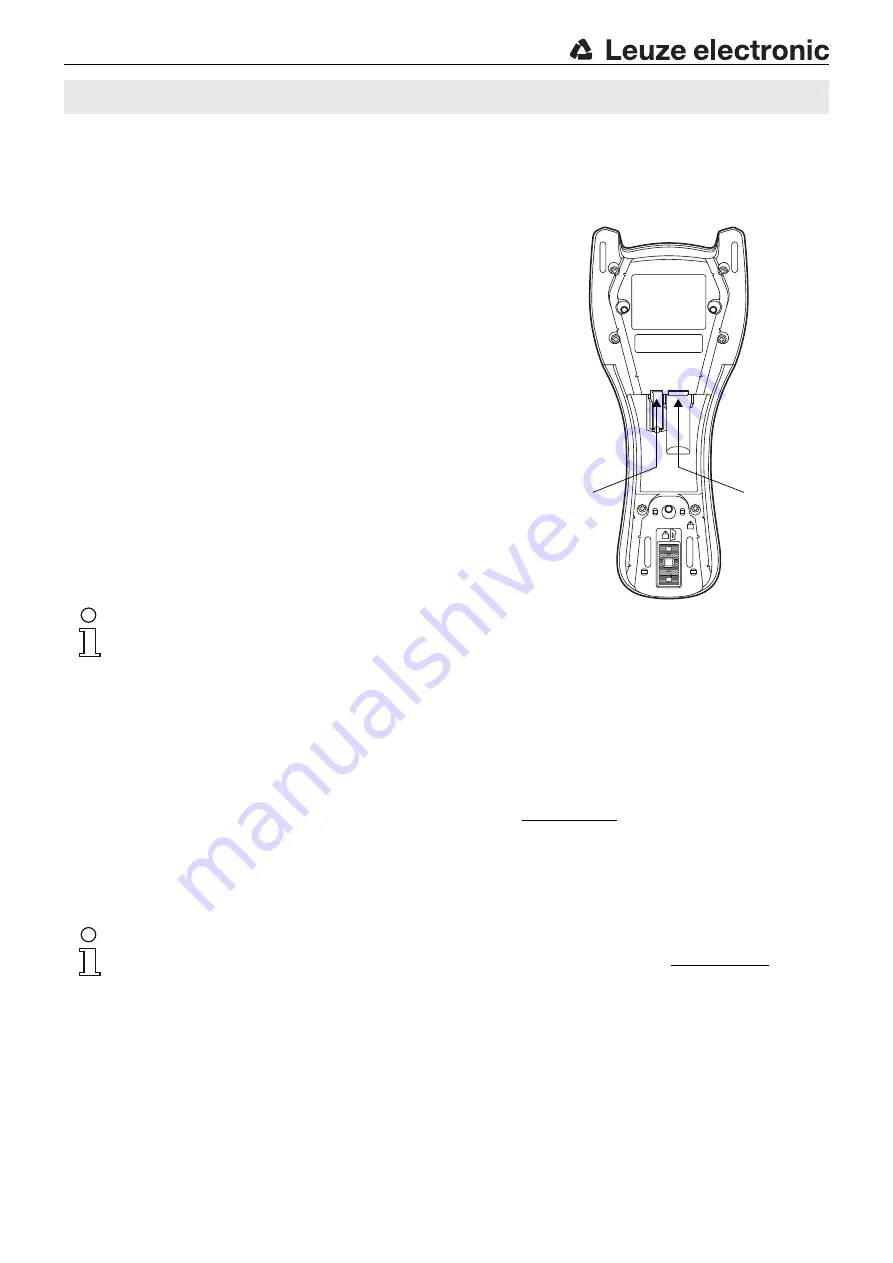
Shown in the adjacent figure are the locations for installing the cables on
the base station. The individual installation steps are described in the fol-
lowing.
1.
To secure the interface cable to the base station, proceed as follows:
plug the RJ 41 connector into the socket on the bottom of the base sta-
tion until the cable clicks into place.
2.
Connect the interface cable to the appropriate connection socket on
the computer.
3.
You may need a power supply unit for supplying voltage if you would
like to charge the hand-held scanner via the base station or use an
RS 232 interface. Use the pin assignments (see "Electrical connection"
on page 1) to select the appropriate cable for your application.
4.
Connect the power supply unit to the power socket.
5.
Use the code for the respective application to configure the hand-held
scanner, see chapter "Parameterization".
6.
Check the operational readiness of the scanner by pointing the scan-
ning surface towards a flat surface and pulling the trigger. A red laser
pattern as well as the red illumination should now be visible. Now scan
a sample label.
The scanner emits an audible signal to confirm that the label has been
read; if necessary, the data are now passed on to the computer.
Notice!
To charge the hand-held scanner, the power supply unit must be plugged in
and the hand-held scanner placed in the base station.
Parameterization
The hand-held scanner can always be configured using bar codes. To do this, the bar code must first be selected on the package
insert and then the trigger actuated in order to read the code. The configuration is then immediately accepted and executed.
Several of the most important configurations are listed in the following.
A second option is to configure the hand-held scanner with the USB and RS 232 interfaces with the aid of the
EZ Config
PC
program. You can download and install this program from our homepage at
www.leuze.com
.
The program can be used to make settings and transfer them to the hand-held scanner. The configuration can also be stored so
that it can be reused at a later time.
More information can also be found in the user's guide.
The standard applications are described and summarized below.
Notice!
Additional information on the device and short instructions can be found on the Internet at www.leuze.com.
Connection for power
supply unit
Connection for interface
cable (RJ 41 socket)
IT 1911i / IT 1981i
2D-code hand-held scanner with Bluetooth for industrial use


