


Protocols for position value output
Leuze electronic
BPS 8
101
TNT
35/7-2
4
V
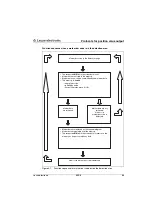
Diagnostic data
By setting the bit
F0
in the request byte (bit 3), the diagnostic data are requested.
If at this point the diagnostic bit
DB
in the status byte is set to 1, the data in the data bytes
correspond to the diagnostic data.
In the response to a diagnostic data request, the bits
CALC
,
DB
and
SLEEP
are set as
follows:
•
CALC
= 1
•
DB
= 1
•
SLEEP
= 0
The diagnostic data are output as an ASCII hex value in the data bytes 1 … 3.
Data byte 1:
First diagnostic data character
Data byte 2:
Second diagnostic data character
Data byte 3:
Third diagnostic data character
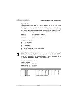
Possible diagnostic data:
E01
= interface problem
E02
= motor problem
E03
= laser problem
E04
= internal problem
E05
= position data outside of measurement range
E09
= invalid control bar code
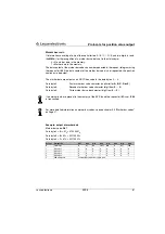
Example: output of diagnostic data
Diagnostic data:
E05
Data byte 1 =
E
= 45
h
= 01000101
b
Data byte 2 =
0
= 30
h
= 00110000
b
Data byte 3 =
5
= 35
h
= 00110101
b
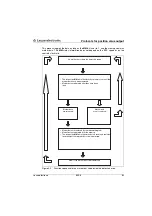
Standby mode
If bit
SLEEP
(bit 6) in status byte is set to 1, the BPS is in Standby mode. In a diagnostic
response during Standby mode, the bits
CALC
,
DB
and
SLEEP
are set as follows:
•
CALC
= 0
•
DB
= 0
•
SLEEP
= 1
In Standby mode, the data bits
P00
to
P20
are always 0.
Byte no.
Designation
Bit 7
Bit 6
Bit 5
Bit 4
Bit 3
Bit 2
Bit 1
Bit 0
0
Status byte
0
SLEEP=0 A1
A0
CALC=1 DB=1
OUT
ERR
1
Data byte 1
0
1
0
0
0
1
0
1
2
Data byte 2
0
0
1
1
0
0
0
0
3
Data byte 3
0
0
1
1
0
1
0
1
4
XOR combination
Bitwise exclusive OR combination of bytes 0 to 3


