Leuze
electronic
Device Description
Leuze electronic
Technical description BCL 90
21
T
N
T 35/
7-
24V
Optional heater
Features:
• Integrated heater (permanently installed)
• Expansion of the area of application of the line scanner to a maximum of -35 °C
(Line scanner with oscillating mirror to a maximum of -35 °C)
• Supply voltage DC 24 V +20%/–10%
• BCL enabling through an internal temperature switch
(switch-on delay about 35 … 40 min for DC 24 V and minimum ambient temperature of -35°)
• required core cross-section (supply voltage): at least 0.75 mm²
Structure:
The heater consists of two parts:
• the front cover heater
• the housing heater
The optional heater is installed and tested to order in the factory. The user cannot install it on site.
Function:
When the supply voltage DC 24 V is applied to the BCL, a temperature switch initially only connects
the heater to electrical power. During the heating phase (around 35 min), when the inside temperature
rises above 7 °C, the temperature switch connects the BCL to the supply voltage. This is followed by
the selftest and the changeover to read operation. The LED "Device Ready" lights up showing overall
readiness for operation.
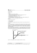
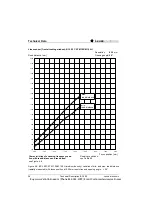
When the inside temperature reaches around 25 °C, another temperature switch turns off the housing
heater to reconnect it when needed. This does not interrupt the read operation. The front cover heater
remains permanently activated. Figure 3.4 shows a diagram of temperature variation in the housing.
Figure 3.4: BCL with heater: diagram of temperature variation in the housing
+40
+30
+20
+10
-10
-20
-30
-40
40 80
Inside temperature [C°]
of the housing
The temperature switch connects the op-
erating voltage to the BCL internally.
Time [min]
Buy: www.ValinOnline.com | Phone 844-385-3099 | Email: [email protected]


