Leroy-Somer LSA R 49.1 Installation And Maintenance Manual Download Page 18

18

INSTALLATION AND MAINTENANCE

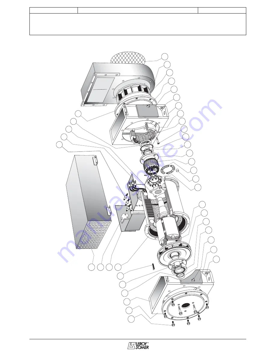
LSA R 49.1 Air/air heat exchanger

ALTERNATORS - Ex II 3 G


SPARE PARTS

4081 en - 09.2006 / a

LEROY-SOMER

5.3 - Exploded view

78

70

90

1

4

132

91

50

30

474

284

68

15

28

22

349

343

107

100

140

140

347

60

77

411

410

82

77

28

36

118

117

120

172

116

79

18

247

249

Summary of Contents for LSA R 49.1

Page 1: ...This manual is to be given to the end user LSA R 49 1 Air air heat exchanger AREP 4 pole ALTERNATORS Ex II 3 G 1 132 474 Installation and maintenance 4081 en 09 2006 a...

Page 2: ...ning symbols Warning symbol for an operation capable of damaging or destroying the machine or surrounding equipment Warning symbol for general danger to personnel Warning symbol for electrical danger...

Page 3: ...ns 5 2 4 Excitation system 5 3 INSTALLATION 3 1 Assembly 6 3 2 Inspection prior to first use 6 3 3 Terminal connection diagrams 7 3 4 Internal coupling 9 3 5 Commissioning 10 3 6 Settings 10 4 SERVICI...

Page 4: ...risks of accidents It is vital that you understand and take notice of the different warning symbols used 1 2 Inspection On receipt of your alternator check that it has not suffered any damage in tran...

Page 5: ...oup 1 class B 2 2 Mechanical characteristics Steel frame End shields in steel pipe in cast iron Greasable ball bearings Mounting arrangement IM 1001 B 34 two bearing with SAE flange and standard cylin...

Page 6: ...s a Dry out the machine for 24 hours in a drying oven at a temperature of approximately 110 C without the AVR b Blow hot air into the air intake having made sure that the machine is rotating with the...

Page 7: ...7 INSTALLATION AND MAINTENANCE LSA R 49 1 Air air heat exchanger ALTERNATORS Ex II 3 G INSTALLATION 4081 en 09 2006 a LEROY SOMER 3 3 Terminal connection diagrams...

Page 8: ...8 INSTALLATION AND MAINTENANCE LSA R 49 1 Air air heat exchanger ALTERNATORS Ex II 3 G INSTALLATION 4081 en 09 2006 a LEROY SOMER 3 3 1 A V R connection...

Page 9: ...3 T6 T5 T2 L2 V D 3 PH Winding 60 Hz 50 Hz 380 415 440 480 A V R terminal 0 380V 6 S Connection code Connection Voltage L L Drawing N LSA491 9 062 N L1 L2 L3 REGULATION REGULATOR 114 114 113 104 104 1...

Page 10: ...connected with the busbar separating the terminals as shown in the terminal connection diagram 3 5 Commissioning The machine can only be started up and used if the installation is in accordance with...

Page 11: ...on probes PTC or PT100 4 2 2 3 Performances We guarantie that the performance of the exchanger complies with the definitions agreed upon ambiant temperature power to be evacuated environmental conditi...

Page 12: ...machine using water or a high pressure washer is strictly prohibited Any problems arising from such treatment are not covered by our warranty The machine should be cleaned with a degreasing agent appl...

Page 13: ...Lack of residual magnetism The alternator builds up but its voltage does not reach the rated value when the battery is removed Check the connection of the voltage reference to the AVR Faulty diodes A...

Page 14: ...tation current of the alternator see nameplate Assembly B Connect a Variac variable power supply and a diode bridge on both exciter field wires 5 and 6 Both these systems should have characteristics w...

Page 15: ...e the air turbine cover 117 Remove the V Ring gasket 249 Remove the inner hood bearing screws 78 Remove the rear flange 82 Remove the ball bearing 70 using a puller with a central screw see fig below...

Page 16: ...the air intake grid 51 Reconnect the field system and close the terminal box 4 7 Table of characteristics Table of average values Alternator 4 poles 50 Hz Standard winding No 6 400V for the excitatio...

Page 17: ...4 Technical Support Service 33 05 45 64 43 69 33 05 45 64 43 67 Fax 33 05 45 64 43 24 Part numbers should be identified from the exploded views and their description from the parts list Our extensive...

Page 18: ...1 Air air heat exchanger ALTERNATORS Ex II 3 G SPARE PARTS 4081 en 09 2006 a LEROY SOMER 5 3 Exploded view 78 70 90 1 4 132 91 50 30 474 284 68 15 28 22 349 343 107 100 140 140 347 60 77 411 410 82 77...

Page 19: ...C T 28 4 Earth terminal 349 1 O ring 30 1 Bush interconnection side 410 1 Front flange 36 1 Bush exciter side 411 8 Fixing screws for front flange 50 1 Air intake grille 474 Departure band 60 1 DE bea...

Page 20: ...MOTEURS LEROY SOMER 16015 ANGOUL ME CEDEX FRANCE 338 567 258 RCS ANGOUL ME S A au capital de 62 779 000 www leroy somer com...

Reviews: