


5
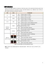
LED Indicators
There are LED light indicators located on the front panel of the industrial Ethernet switch that
display the power status and network status. Each LED indicator has a different color and has its
own specific meaning, see below in Table 2.1.
LED
Color
Description
P1
Green
On
Power input 1 is active
Off
Power input 1 is inactive
P2
Green
On
Power input 2 is active
Off
Power input 2 is inactive
Fault
Red
On
Power input 1 or 2 is inactive
Off
Power input 1 and 2 are both functional
SFP Port
LNK/ACT
(Port
17 to 18)
Green
On
Connected to network, 1000Mbps
Flashing
Networking is active
Off
Not connected to network
Amber
On
Connected to network, 100Mbps
Flashing Networking is active
Off
Not connected to network
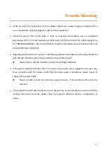
LAN Port
(Port 1 to 16)
Green
On
Connected to network, 1000Mbps
Flashing
Networking is active
Off
Not connected to network
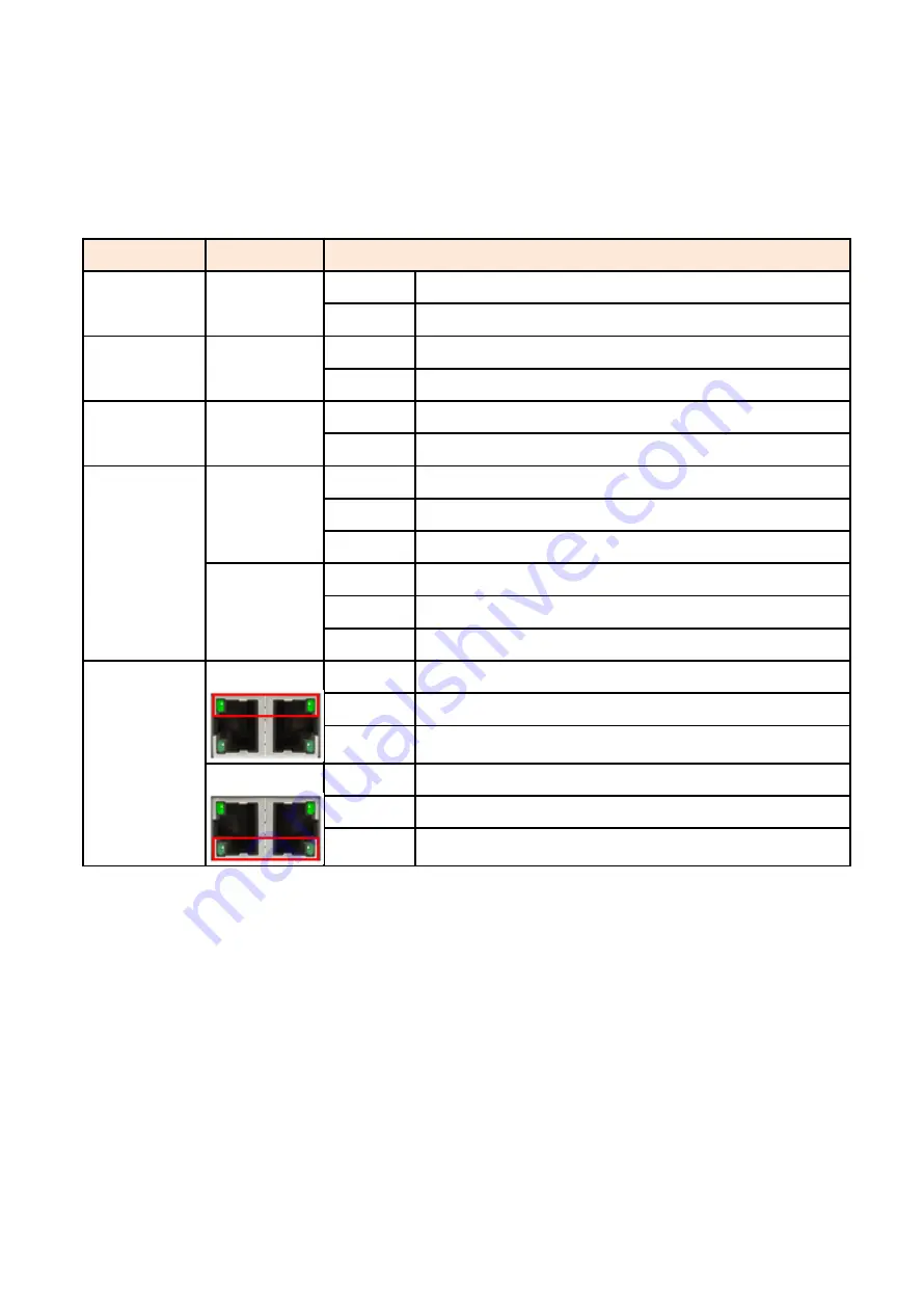
Green
On
Connected to network, 10/100Mbps
Flashing
Networking is active
Off
Not connected to network
Table 2.1: LED Indictors for PG2-2004-SFP Series
Note
: “P1/P2" is the abbreviation for "Power1/Power2", "LNK" is for "Link", and "ACT" is for
"Activity".


