Leonton EG2-2004-SFP Series User Manual Download Page 21

17 

Trouble Shooting 


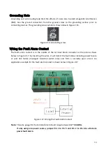
Verify you have the right power cord or adapter. Never use a power supply or adapter with a 
non-compliant DC output voltage or it will burn the equipment.


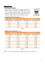
Select the proper UTP or STP cable in order to construct the network. Use an unshielded 
twisted-pair (UTP) or shield twisted-pair (STP) cable for RJ-

45 connections: 100Ω Category 5e 

for 10M/100/1000Mbps. Also be sure that the length of any twisted-pair connection does not 
exceed 100 meters (328 feet).


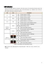
Diagnosing LED Indicators: To assist in identifying problems, the switch can be easily monitored 
with the LED indicators which help to identity if any problems exist.


Please refer to the LED Indicators section for LED light indication.


If the power indicator LED does not turn on when the power cord is plugged in, the user may 
have a problem with the power cord. Check for loose power connections, power losses or 
surges at the power outlet.


Please contact Leonton for technical support service, if the problem still cannot be 
resolved.


If the industrial switch LED indicators are normal and the connected cables are correct but the 
packets still cannot transmit, please check the system’s Ethernet devices’ configuration or 
status.


Summary of Contents for EG2-2004-SFP Series

Page 1: ...Leonton EG2 2004 SFP Series EG2 2004 SFP EG2 2004 SFP T User Manual Version 1 0...

Page 2: ...t not limited to the implied warranties of merchantability and fitness for a particular purpose Leonton Technologies Co Ltd may make improvements and or changes to the product and or specifications of...

Page 3: ...the equipment off and on the user is encouraged to try to correct the interference by one or more of the following measures Reorient or relocate the receiving antenna Increase the separation between t...

Page 4: ...ption 3 Physical Dimensions 3 Front Panel 4 Top View 4 LED Indicators 5 Ethernet Ports 6 Cabling 7 Wiring the Power Inputs 9 Wiring the Fault Alarm Contact 10 Mounting Installation 11 DIN Rail Mountin...

Page 5: ...this series is designed to meet any needs for industrial automation application and harsh environments Key Features Interface Performance All Copper ports support auto MDI MDI X function Embedded 16...

Page 6: ...tion If the DC voltage is supplied by an external circuit please use a protection device on the power supply input Supply by UL Listed industrial use power The industrial Ethernet switch s hardware sp...

Page 7: ...3 Hardware Description Physical Dimensions Figure 2 1 below shows the physical dimensions of EG2 2004 SFP series W x H x D is 67mm x 142mm x 99mm Figure 2 1 EG2 2004 SFP Series Physical Dimensions...

Page 8: ...shown below in Figure 2 2 Figure 2 2 The Front Panel of EG2 2004 SFP Series Top View Figure 2 3 below shows the top panel of the EG2 2004 SFP series switch that is equipped with one 6 pin removal ter...

Page 9: ...is inactive Off Power input 1 and 2 are both functional SFP Port LNK ACT Port 17 to 18 Green On Connected to network 1000Mbps Flashing Networking is active Off Not connected to network Amber On Conne...

Page 10: ...raight Through Cable Pin Number Signal Pin Number Signal Pin Number Signal Pin Number Signal 1 RX 3 TX 1 RX 1 TX 2 RX 6 TX 2 RX 2 TX 3 TX 1 RX 3 TX 3 RX 6 TX 2 RX 6 TX 6 RX Table 2 2 1000BASE T RJ 45...

Page 11: ...telecommunication and data communication applications Note Please employ optional optical transceiver SFP that complies with IEC 60825 1 and classified as Class 1 laser product To connect the transce...

Page 12: ...ure 2 11 Figure 2 11 LC Connector to the Transceiver To remove the LC connector from the transceiver please follow the steps shown below Step 1 Press the upper side of the LC connector from the transc...

Page 13: ...Insert the positive and negative wires into the PWR1 V1 V1 and PWR2 V2 V2 contacts on the terminal block connector as shown below in Figure 2 14 Figure 2 14 Power Terminal Block Step 2 Tighten the wi...

Page 14: ...is in the middle of the terminal block connector as the picture shows below in Figure 2 17 By inserting the wires it will detect the fault status including power failure or port link failure managed...

Page 15: ...ure 3 1 The Rear Side of the Switch and DIN Rail Bracket Follow the steps below to learn how to hang the industrial Ethernet switch Step 1 Use the screws to install the DIN Rail bracket on the rear si...

Page 16: ...ull down the bracket on to the rail as shown below in Figure 3 3 Figure 3 3 Stable the Switch on DIN Rail Step 5 Check if the bracket is mounted tightly on the rail Step 6 To remove the industrial Eth...

Page 17: ...ckets on the top and bottom of the industrial Ethernet switch Step 3 Use the screws to screw the wall mounting bracket on the industrial Ethernet switch Step 4 Use the hook holes at the corners of the...

Page 18: ...14 Figure 3 5 Wall Mounting Bracket Dimensions...

Page 19: ...o the Mounting Installation section Step 4 Power on the industrial Ethernet switch and then the power LED light will turn on If you need help on how to wire power please refer to the Wiring the Power...

Page 20: ...l as other cables Be careful when handling them so as to not trip over Do not under any circumstance insert foreign objects of any kind into the heat dissipation holes located in the different faces o...

Page 21: ...assist in identifying problems the switch can be easily monitored with the LED indicators which help to identity if any problems exist Please refer to the LED Indicators section for LED light indicat...

Reviews: