Leonton CEG2-0800 Series Hardware User Manual Download Page 5


OVERVIEW


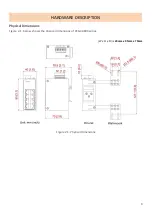
This series is rated IP30 and installation by DIN Rail. Each unit of this industrial gigabit unmanaged 
Ethernet switch series has 8*10/100/1000Tx Gigabit Ethernet ports, which the RJ-45 interface provides 
auto detection of MDI or MDI-X.


In order to prevent unregulated voltage, this series provides high EFT and 

ESD protection which also allows it to function in harsh environments, as well as support power 
redundancy with a dual power input design with reverse polarity protection. 
Providing with an operating temperature of -10°C ~ 65°C, and another with a wide operating temperature 
of -40°C ~ 75°C, this series is designed to meet any needs for industrial automation application and harsh 
environments. 


Key Features 

Interface & Performance 


All Copper ports support auto MDI/MDI-X function 


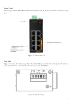
Embedded 8*10/100/1000Tx Gigabit Ethernet 


Store-and-forward switching architecture 


8K MAC Address Table 


Support 9,216 bytes Jumbo Frame 


512 bits memory buffer 

Power Input 


Dual 12-48VDC redundant power inputs, with SELV output certified by UL61010-2-201 


1 removable 6-contact terminal block  


Max. current 3.5A 

Certification 


CE/FCC 


UL 61010-1 


UL 61010-2-201 

Operating Temperature 


Standard operating temperature model: -10°C ~ 65°C 


Extended operating temperature model (-T): -40°C ~ 75°C 

Case/Installation 


IP30 protection (not certified by UL) 


DIN-Rail and wall mount design 


Installation in a pollution degree 2 industrial environment 


Standalone installation 

Summary of Contents for CEG2-0800 Series

Page 1: ...CEG2 0800 CEG2 0800 T...

Page 2: ...t not limited to the implied warranties of merchantability and fitness for a particular purpose Leonton Technologies Co Ltd may make improvements and or changes to the product and or specifications of...

Page 3: ...tions FCC Ces limites sont con ues pour fournir une protection raisonnable contre toutes interf rences nuisibles dans un milieu r sidentiel Cet quipement g n re utilise et peut mettre de l nergie de f...

Page 4: ...RE DESCRIPTION 3 Physical Dimensions 3 Front Panel 4 Top View 4 LED Indicators 5 Ethernet Ports 6 Cabling 7 Wiring the Power Inputs 7 Grounding Note 8 MOUNTING INSTALLATION 9 DIN Rail Mounting 9 Wall...

Page 5: ...s designed to meet any needs for industrial automation application and harsh environments Key Features Interface Performance All Copper ports support auto MDI MDI X function Embedded 8 10 100 1000Tx G...

Page 6: ...protection sur l entr e d alimentation Fourniture par courant industriel homologu UL Les sp cifications mat rielles les ports les informations de c blage et l installation du c blage du convertisseur...

Page 7: ...3 HARDWARE DESCRIPTION Physical Dimensions Figure 2 1 below shows the physical dimensions of CEG2 0800 series W x H x D is 40mm x 95mm x 70mm Figure 2 1 Physical Dimensions...

Page 8: ...ed Ethernet switch is shown below in Figure 2 2 Figure 2 2 The Front Panel Top View Figure 2 3 below shows the top panel of the CEG2 0800 series switch that is equipped with one 6 pin removal terminal...

Page 9: ...s LED Color Description P1 Green On Power input 1 is active Off Power input 1 is inactive P2 Green On Power input 2 is active Off Power input 2 is inactive Fault Red On Power input 1 or 2 is inactive...

Page 10: ...raight Through Cable Pin Number Signal Pin Number Signal Pin Number Signal Pin Number Signal 1 RX 3 TX 1 RX 1 TX 2 RX 6 TX 2 RX 2 TX 3 TX 1 RX 3 TX 3 RX 6 TX 2 RX 6 TX 6 RX Table 2 2 1000BASE T RJ 45...

Page 11: ...rt the positive and negative wires into the PWR1 V1 V1 and PWR2 V2 V2 contacts on the terminal block connector as shown below in Figure 2 4 Figure 2 4 Power Terminal Block Step 2 Tighten the wire clam...

Page 12: ...1 to Pin 5 and Pin 2 to Pin 6 to eliminate power fault alarm Attention Le calibre des fils du bornier doit tre compris entre 12 et 24 AWG Si vous n utilisez qu une seule source d alimentation jumelez...

Page 13: ...3 1 The Rear Side of the Switch and Wall Mounting Bracket Follow the steps below to learn how to hang the industrial Ethernet switch Step 1 Use the screws to install the DIN Rail bracket on the rear...

Page 14: ...ull down the bracket on to the rail as shown below in Figure 3 3 Figure 3 3 Stable the Switch on DIN Rail Step 5 Check if the bracket is mounted tightly on the rail Step 6 To remove the industrial Eth...

Page 15: ...strial Ethernet switch Step 3 Use the screws to screw the wall mounting bracket on the industrial Ethernet switch Step 4 Use the hook holes at the corners of the wall mounting bracket to hang the indu...

Page 16: ...Installation section Step 4 Power on the industrial Switch and then the power LED light will turn on If you need help on how to wire power please refer to the Wiring the Power Inputs section Please re...

Page 17: ...est de la responsabilit de l assembleur du syst me Caution This is an OPEN TYPE module and should be installed in a final safety enclosure characteristic Attention Il s agit d un module de TYPE OUVERT...

Page 18: ...which help to identity if any problems exist Please refer to the LED Indicators section for LED light indication If the power indicator LED does not turn on when the power cord is plugged in the user...

Reviews: