Leonton CEG2-0800 Series Hardware User Manual Download Page 18


14 

TROUBLE SHOOTING


● 

Verify you have the right power cord or adapter. Never use a power supply or adapter with a non-
compliant DC output voltage or it will burn the equipment.


● 

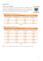
Select the proper UTP or STP cable in order to construct the network. Use an unshielded twisted-pair 
(UTP) or shield twisted-pair (STP) cable for RJ-

45 connections: 100Ω Category 5e for 

10M/100/1000Mbps. Also be sure that the length of any twisted-pair connection does not exceed 
100 meters (328 feet).


● 

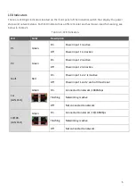
Diagnosing LED Indicators: To assist in identifying problems, the Switch can be easily monitored with 
the LED indicators which help to identity if any problems exist.


Please refer to the LED Indicators section for LED light indication.


● 

If the power indicator LED does not turn on when the power cord is plugged in, the user may have a 
problem with the power cord. Check for loose power connections, power losses or surges at the 
power outlet.


Please contact Leonton for technical support service, if the problem still cannot be resolved.


● 

If the industrial Switch LED indicators are normal and the connected cables are correct but the 

packets still cannot transmit, please check the system’s Ethernet devices’ configuration or status.


For any repair or maintenance needs, please contact us. 

LEONTON TECHNOLOGIES, CO., LTD 

9F-1, No.43, Fuxing Rd., Xindian Dist.,  

New Taipei City, 231,  

Taiwan 

TEL: +886 2 22183113 

FAX: +886 2 22187391 

Summary of Contents for CEG2-0800 Series

Page 1: ...CEG2 0800 CEG2 0800 T...

Page 2: ...t not limited to the implied warranties of merchantability and fitness for a particular purpose Leonton Technologies Co Ltd may make improvements and or changes to the product and or specifications of...

Page 3: ...tions FCC Ces limites sont con ues pour fournir une protection raisonnable contre toutes interf rences nuisibles dans un milieu r sidentiel Cet quipement g n re utilise et peut mettre de l nergie de f...

Page 4: ...RE DESCRIPTION 3 Physical Dimensions 3 Front Panel 4 Top View 4 LED Indicators 5 Ethernet Ports 6 Cabling 7 Wiring the Power Inputs 7 Grounding Note 8 MOUNTING INSTALLATION 9 DIN Rail Mounting 9 Wall...

Page 5: ...s designed to meet any needs for industrial automation application and harsh environments Key Features Interface Performance All Copper ports support auto MDI MDI X function Embedded 8 10 100 1000Tx G...

Page 6: ...protection sur l entr e d alimentation Fourniture par courant industriel homologu UL Les sp cifications mat rielles les ports les informations de c blage et l installation du c blage du convertisseur...

Page 7: ...3 HARDWARE DESCRIPTION Physical Dimensions Figure 2 1 below shows the physical dimensions of CEG2 0800 series W x H x D is 40mm x 95mm x 70mm Figure 2 1 Physical Dimensions...

Page 8: ...ed Ethernet switch is shown below in Figure 2 2 Figure 2 2 The Front Panel Top View Figure 2 3 below shows the top panel of the CEG2 0800 series switch that is equipped with one 6 pin removal terminal...

Page 9: ...s LED Color Description P1 Green On Power input 1 is active Off Power input 1 is inactive P2 Green On Power input 2 is active Off Power input 2 is inactive Fault Red On Power input 1 or 2 is inactive...

Page 10: ...raight Through Cable Pin Number Signal Pin Number Signal Pin Number Signal Pin Number Signal 1 RX 3 TX 1 RX 1 TX 2 RX 6 TX 2 RX 2 TX 3 TX 1 RX 3 TX 3 RX 6 TX 2 RX 6 TX 6 RX Table 2 2 1000BASE T RJ 45...

Page 11: ...rt the positive and negative wires into the PWR1 V1 V1 and PWR2 V2 V2 contacts on the terminal block connector as shown below in Figure 2 4 Figure 2 4 Power Terminal Block Step 2 Tighten the wire clam...

Page 12: ...1 to Pin 5 and Pin 2 to Pin 6 to eliminate power fault alarm Attention Le calibre des fils du bornier doit tre compris entre 12 et 24 AWG Si vous n utilisez qu une seule source d alimentation jumelez...

Page 13: ...3 1 The Rear Side of the Switch and Wall Mounting Bracket Follow the steps below to learn how to hang the industrial Ethernet switch Step 1 Use the screws to install the DIN Rail bracket on the rear...

Page 14: ...ull down the bracket on to the rail as shown below in Figure 3 3 Figure 3 3 Stable the Switch on DIN Rail Step 5 Check if the bracket is mounted tightly on the rail Step 6 To remove the industrial Eth...

Page 15: ...strial Ethernet switch Step 3 Use the screws to screw the wall mounting bracket on the industrial Ethernet switch Step 4 Use the hook holes at the corners of the wall mounting bracket to hang the indu...

Page 16: ...Installation section Step 4 Power on the industrial Switch and then the power LED light will turn on If you need help on how to wire power please refer to the Wiring the Power Inputs section Please re...

Page 17: ...est de la responsabilit de l assembleur du syst me Caution This is an OPEN TYPE module and should be installed in a final safety enclosure characteristic Attention Il s agit d un module de TYPE OUVERT...

Page 18: ...which help to identity if any problems exist Please refer to the LED Indicators section for LED light indication If the power indicator LED does not turn on when the power cord is plugged in the user...

Reviews: