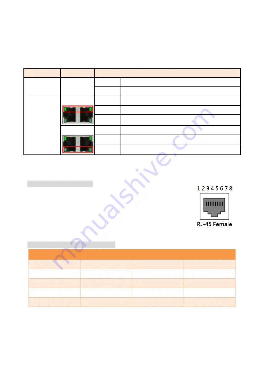
background image

LED Indicators 

There  are  LED  light  indicators  located  on  the  front  panel  of  the  industrial  Ethernet  switch  that 
display the power status and network status. Each LED indicator has a different color and has its 
own specific meaning, see below in Table 2.1.


LED


Color


Description


PWR


Green


On


Power input 1 or 2 is active


Off


Power input 1 or 2 is inactive


LAN Port 

LINK/ACT/SPEED


Green


On


Connected to network, 1000Mbps


Flashing


Networking is active


Off


Not connected to network


Green


On


Connected to network, 10/100Mbps


Flashing


Networking is active


Off


Not connected to network


Table 2.1: LED Indictors for CEG2-0500 Series


Ethernet Ports 

RJ-45 Ports


(Auto MDI/MDIX)


The  RJ-45  ports  are  auto-sensing  for  10Base-T,  100Base-TX  or 
1000Base-T  devices  connections.  Auto  MDI/MDIX  means  that  the 
switch  can  connect  to  another  switch  or  workstation  without 
changing the straight-through or crossover cabling. See the figures 
as below for straight-through and crossover cabling schematics. 


10/100BASE-T(X) RJ-45 Pin Assignments

 (Table 2.2) 

Crossover Cable 

Straight Through Cable 

Pin Number / Signal 

Pin Number / Signal 

Pin Number / Signal 

Pin Number / Signal 

1 / RX+ 

3 / TX+ 

1 / RX+ 

1 / TX+ 

2 / RX- 

6 / TX- 

2 / RX- 

2 / TX- 

3 / TX+ 

1 / RX+ 

3 / TX+ 

3 / RX+ 

6 / TX- 

2 / RX- 

6 / TX- 

6 / RX- 


Table 2.2 


Summary of Contents for CEG2-0500 Series

Page 1: ...Leonton CEG2 0500 Series CEG2 0500 CEG2 0500 T User Manual Version 1 0...

Page 2: ...t not limited to the implied warranties of merchantability and fitness for a particular purpose Leonton Technologies Co Ltd may make improvements and or changes to the product and or specifications of...

Page 3: ...the equipment off and on the user is encouraged to try to correct the interference by one or more of the following measures Reorient or relocate the receiving antenna Increase the separation between t...

Page 4: ...2 Hardware Description 3 Physical Dimensions 3 Front Panel 4 Top View 4 LED Indicators 5 Ethernet Ports 5 Cabling 6 Wiring the Power Inputs 6 Mounting Installation 8 DIN Rail Mounting 8 Wall Mounting...

Page 5: ...operating temperature of 40 C 75 C this series is designed to meet any needs for industrial automation application and harsh environments Key Features Interface Performance All Copper ports support au...

Page 6: ...on If the DC voltage is supplied by an external circuit please use a protection device on the power supply input Supply by UL Listed industrial use power The industrial Ethernet switch s hardware spec...

Page 7: ...3 Hardware Description Physical Dimensions Figure 2 1 below shows the physical dimensions of CEG2 0500 series W x H x D is 26mm x 95mm x 75mm Figure 2 1 Physical Dimensions...

Page 8: ...ged Ethernet switch is shown below in Figure 2 2 Figure 2 2 The Front Panel Top View Figure 2 3 below shows the top panel of the CEG2 0500 series switches that is equipped with one 4 pin removal termi...

Page 9: ...00Mbps Flashing Networking is active Off Not connected to network Table 2 1 LED Indictors for CEG2 0500 Series Ethernet Ports RJ 45 Ports Auto MDI MDIX The RJ 45 ports are auto sensing for 10Base T 10...

Page 10: ...3 Note and signs represent the polarity of the wires that make up each wire pair Cabling Use the four twisted pair category 5e or the above cabling for RJ 45 port connections The cable between the sw...

Page 11: ...screws to prevent the wires from loosening as shown below in Figure 2 10 Figure 2 10 Power Terminal Block Note Only use copper conductors 60 75 C tighten to 5 lbs The wire gauge for the terminal block...

Page 12: ...ure 3 1 The Rear Side of the Switch and DIN Rail Bracket Follow the steps below to learn how to hang the industrial Ethernet switch Step 1 Use the screws to install the DIN Rail bracket on the rear si...

Page 13: ...ull down the bracket on to the rail as shown below in Figure 3 3 Figure 3 3 Stable the Switch on DIN Rail Step 5 Check if the bracket is mounted tightly on the rail Step 6 To remove the industrial Eth...

Page 14: ...Step 2 Place the wall mounting brackets on the top and bottom of the industrial Ethernet switch Step 3 Use the screws to screw the wall mounting bracket on the industrial Ethernet switch Step 4 Use th...

Page 15: ...11 Below in Figure 3 5 are the dimensions of the wall mounting bracket Figure 3 5 Wall Mounting Bracket Dimensions...

Page 16: ...the Mounting Installation section Step 4 Power on the industrial Ethernet switch and then the power LED light will turn on If you need help on how to wire power please refer to the Wiring the Power I...

Page 17: ...assist in identifying problems the switch can be easily monitored with the LED indicators which help to identity if any problems exist Please refer to the LED Indicators section for LED light indicat...

Reviews: