background image

Safety instructions

Residual hazards

2


l

 9

BA 13.0008 − EN      2.1

2.2

Residual hazards

Protection of persons

The motor surfaces can become very hot. Danger of burns when touching!

l

Install a guard, if necessary.

High−frequency voltages can be capacitively transferred to the motor housing
through the inverter supply.

l

Carefully earth the motor housing.

Danger of unintentional starting or electrical shocks

l

Perform connection work only in the de−energised state, only with motor
in standstill.

l

Built−in brakes are not fail−safe brakes.

Device protection

Built−in thermal detectors are 

not a full protection

 for the machine.

l

If necessary, limit the maximum current, perform a function block
interconnection with disconnection after a few seconds of operation with I
> I

N

, particularly if a danger of blocking exists.

l

The integrated overload protection does not prevent overload under all
conditions!

Built−in brakes are 

not fail−safe brakes

 .

l

Speed reduction is possible.

Fuses are not a motor protection.

l

Use current−dependent motor protection switches for average operating
frequency

l

Use built−in thermal detectors at high operating frequency.

Excessive torques lead to a break of the motor shaft or demagnetisation

l

Do not exceed the maximum torques according to the catalogue.

Lateral forces from the motor shaft are possible.

l

Perfectly align shafts of motor and driving machine to each other.

l

Speeds >3000 min

−1 

destroy the motor.

Fire protection

Fire hazard

l

Prevent contact with combustible substances.

2.3

Safety instructions for low−voltage machinery

in conformity with the Low−Voltage Directive 73/23/EEC

1. General

Low−voltage machines have dangerous, live and rotating parts as well as possibly hot
surfaces. All operations serving transport, connection, commissioning and maintenance
are to be carried out by skilled, responsible technical personnel (observe prEN 50110−1/
VDE 0105; IEC 364). Improper handling can cause severe injuries or material damage.

2. Application as directed

These low−voltage machines are intended for industrial and commercial installations.
They comply with the harmonised standards of the series EN60034 (VDE 0530). Their use
in hazardous areas is prohibited unless they are expressly intended for such use (follow
additional instructions).

The enclosures 

£

 IP 23 are by no means intended for outdoor use. Air cooled designs are rated

for ambient temperatures between −20°C and +40°C and altitudes of 

£

 1000 m amsl. Check

indications on the nameplate and, if other observe them. The conditions on site must
correspond to all nameplate data.

Low−voltage machines are components for installation in machinery as defined in the
Machinery Directive 89/392/EEC. Commissioning is prohibited until conformity of the end
product with this Directive has been established (observe i.a. EN 60204−1).

Buy: www.ValinOnline.com | Phone 844-385-3099 | Email: [email protected]

Summary of Contents for SDSGA

Page 1: ...BA 13 0008 EN 5 E 5 E Operating Instructions l SDSGA Inverter optimised asynchronous motors Buy www ValinOnline com Phone 844 385 3099 Email CustomerService valin com...

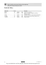
Page 2: ...for pilot series 409413 1 1 04 2001 TD09 Chapter 3 2 Extension of application conditions All chapters Revised 452930 1 2 04 2002 TD09 Extended by chapter 5 2 1 type and quantity of lubricant 13209536...

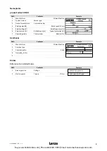
Page 3: ...ted frequency Hz 6 Rated current A Rated torque mF Type of protection IP 7 Operating mode Thermal class Material No Gearboxes Field Contents Example 1 Manufacturer CE identification 2 Gearbox type 3 C...

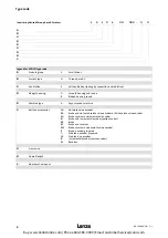
Page 4: ...nchronous machine 5 Built on accessories AG BA BG BI BR BS BW B G XX IG RS Absolute value encoder Brake and sin cos absolute value encoder or SSI absolute value encoder Brake resolver and incremental...

Page 5: ...1 1 Shaft loads 14 3 2 General data and operating conditions 15 3 2 1 Other application conditions 16 4 Mechanical installation 18 4 1 Transport storage and installation 18 4 2 Site 19 5 Electrical in...

Page 6: ...and notes relevant for them The Operating Instructions must always be complete and perfectly readable 1 1 1 Terminology used Term In the following text used for Motor Inverter optimised motor of type...

Page 7: ...process related notes and circuit sections used in these instructions are suggestions whose suitability for the respective application must be checked Lenze assumes no guarantee for the suitability o...

Page 8: ...nel have the Operating Instructions available for all corresponding operations that non qualified personnel are prohibited from working with and on the drive system Skilled personnel Skilled personnel...

Page 9: ...align shafts of motor and driving machine to each other l Speeds 3000 min 1 destroy the motor Fire protection Fire hazard l Prevent contact with combustible substances 2 3 Safety instructions for low...

Page 10: ...provide pipe connections Mounting positions with shaft end at top must be protected with a cover which avoids the ingression of foreign particles into the fan Free circulation of the cooling air must...

Page 11: ...hine in problematic situations If the drive is exposed to dirt clean it regularly Regrease the bearings using the relubrication facility while the low voltage machine is running Observe the saponifica...

Page 12: ...to prevent dangerous situations Pictograph and signal word Meaning Danger Danger of personal injury through dangerous electrical voltage Reference to an imminent danger that may result in death or ser...

Page 13: ...ze servo inverters of the 9300 series with an inverter input voltage mains voltage of 400 V and an inverter frequency of 8 kHz Note The motors can also be connected to inverters others than inverters...

Page 14: ...U V Ir A Fr1 Fr2 N Fa N l cosj f HZ mmotor appro x kg SDSGARSLL 047 22 75 6000 2700 0 27 1 0 0 41 230 400 0 90 0 52 350 300 250 0 5 100 3 0 056 22 240 2790 0 81 3 2 1 404 1 49 0 86 560 530 430 0 714...

Page 15: ...lass F 155 C to DIN IEC 34 VDE 0530 The insulation will be weakened or destroyed when the limit temperature is exceeded Tropical insulation Not guaranteed Permissible voltage 1 5 kV peak value 5 kV ms...

Page 16: ...specified in Tab 2 Torques as high as indicated can be reached through appropriate motor controller combinations Excessive torques might result in a break of the motor shaft Note Excessive axial and r...

Page 17: ...itions Cooling air temperature C 1 40 45 50 55 60 Power derating k 1 1 00 0 95 0 90 0 83 0 77 Installation height amsl in m 2 1000 2000 3000 4000 5000 Power derating kh 2 1 00 0 92 0 83 0 77 0 67 1 De...

Page 18: ...ry renew it Installation The motors are tested for operation and are ready for use Preparations Remove the corrosion protection from the steel parts Check for transport damage and fix key if necessary...

Page 19: ...emperatures up to 40 C in case of other temperatures see chapter 3 2 1 Installation height up to 1000 m amsl in case of other installation heights see chapter 3 2 1 Ensure unimpeded ventilation The ex...

Page 20: ...xtremely long cables are used we recommend to use the next cable cross section up to reduce the power losses Observe the minimum cross sections to DIN VDE 0298 4 Establish the electrical connection as...

Page 21: ...mbly or disassembly Motors with B side attachments brakes and or encoders are assembled electrically connected and tested for operation Observe the corresponding Operating Instructions 5 2 Gearbox mou...

Page 22: ...After the shaft seal 51 has been mounted mount the worm Ensure stability of the motor shaft end when pinning 50 Use the screws and washers in the assembly kit for the motor to mount the gearbox to the...

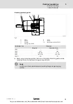
Page 23: ...42 Gearbox type size Dimensions Flange size Dimension x in mm SPL42 31 SPL52 C80 38 6 SPL62 C80 C90 43 43 SPL81 C90 C105 51 6 58 6 SPL120 C105 73 7 When using a planetary gearbox the force is transmit...

Page 24: ...Ohm 72 20 9 10 8 5 C0085 Xleak mH 267 103 50 26 C0086 COMMON 0 C0087 nr 1 min 2700 2790 2800 2825 C0088 Ir A 0 52 0 90 0 86 1 50 1 23 2 12 1 74 3 C0089 fr Hz 100 C0090 Ur V 390 230 390 230 390 230 39...

Page 25: ...name Connection to Pin assignment SDSGALL047 22 SDSGALL056 22 SDSGALL063 22 SDSGALL063 32 1 B Track B SIN 2 A Track A inverted COS 3 A Track A 4 5 V Supply 5V 8V 5 GND Ground 6 Z Zero track inverted...

Page 26: ...foreign particles ingress into the motor 6 1 Before switching on Before commissioning Before commissioning after a longer standstill Before commissioning after repair and maintenance of the motor Stop...

Page 27: ...sary provide protection against contact to protect yourself from burns Observe cooling times Depending on the application conditions the drive must be checked frequently during operation Please observ...

Page 28: ...ately after switch off and standstill of the motor Procedure 1 Remove the plug in connector X10 For terminal box designs interrupt the power supply between inverter and motor 2 Measure the resistance...

Page 29: ...7 l 29 BA 13 0008 EN 2 1 7 2 Repair It is recommended to have all repairs performed by Lenze Service Delivery of spare parts is available upon request Buy www ValinOnline com Phone 844 385 3099 Email...

Page 30: ...mes Wrong direction of rotation of the motor correct display at controller Reversed motor cable and resolver cable Exchange 2 phases of the motor cable and the COS COS connections of the resolver Moto...

Reviews: