

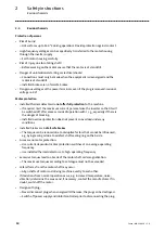


Mechanical installation
Mounting of g500 short/servo adapters with clamping connection
Mounting of motors on gearboxes with mounting flange
22
Lenze ¯ MA 12.0018 ¯ 2.0
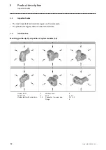
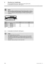
4.4.4
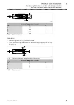
Mounting of motors on gearboxes with mounting flange and flexible
coupling (drive−end version N)
Fig. 7
Input side design N
Spider / gear rim
1
Locking screw
Coupling hub
2
Keyway
Drive size
Motor shaft
Assembly
dimension
Standard hub
Locking screw
Clamping hub
Key
1)
Clamping ring hub
D
[ mm ]
max. l
[ mm ]
M
[ mm ]
Thread
[ mm ]
Tightening
torque
[ Nm ]
Thread
[ mm ]
Tightening
torque
[ Nm ]
DIN 6885/1
[ mm ]
Thread
[ mm ]
Tightening
torque
[ Nm ]
1A
11
23
23
M4
1.5
M3
1.34
*
M3
1.34
1B
14
40
25
M5
2.0
M6
10.5
B5 x 5 x 16
M4
2.9
2B
11
23
23
M4
1.5
M3
1.34
*
M3
1.34
1C
19
40
25
M5
2.0
M6
10.5
B6 x 6 x 16
M4
2.9
2C
14
40
25
B5 x 5 x 16
3C
14
40
25
4C
14
40
25
6C
11
40
25
−−−
−−−
*
−−−
−−−
7C
19
40
25
M5
2.0
B6 x 6 x 16
M4
2.9
1D
24
60
30
M6
10.5
B8 x 7 x 18
M5
6
2D
19
60
30
B6 x 6 x 18
1E
28
60
30
B8 x 7 x 18
2E
24
60
30
3E
19
60
30
B6 x 6 x 18
4E
24
50
50
*
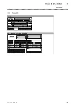
Tab. 3
Attachment of motors to gearboxes with mounting flange
* Use original key for the motor
1)
Key for standard hub and clamping hub
Summary of Contents for g500 Series
Page 43: ...Notes 43 Lenze MA 12 0018 2 0...


