5 Mechanical installation
EDK82ZBC DE/EN/FR 3.1
46
H1_MechINS-install_de
8200 vector
E82ZWLxxx
E82ZBB
E82ZBC
z
y
w x
v
t
u
s
88888
8888
888
8
a
b
c
d
e
j g f k i h
PS
m n o
p
q r
Hi
Hz
%sh
rpm
°C
W
m
A
V
Lo
z
y
w x
v
t
u
s
888
00
0050
000
1
a
b
c
d
e
j
g
f k i h
PS
m n o
p
q r
Hi
Hz
%sh
rpm
°C
W
m
A
V
Lo
z
y
w x
v
t
u
s
888
00
0050
000
1
a
b
c
d
e
j
g
f k i h
PS
m n o
p
q r
Hi
Hz
%sh
rpm
°C
W
m
A
V
Lo
8888
8
8888
888
8
a
b
c
d
e
j
g
f
k
i
h
PS
m
n
op
q
r
Hi
Hz
%sh
rpm
°C
W
m A
V
Lo
z
y
w x
v
t
u
s
88888
8888
888
8
a
b
c
d
e
j g f k i h
PS
m n op
q r
Hi
Hz
%sh
rpm
°C
W
m
A
V
Lo
z
y
w x
v
t
u
s
888
00
0050
000
a
b
c
d
e
j
g
f k i h
PS
m n o
p
q r
Hi
Hz
%sh
rpm
°C
W
m
A
V
Lo
0
1
2
3
E82ZBC018
c
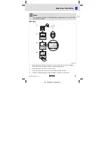
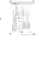
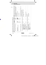
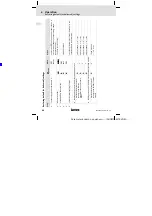
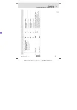
Connect the keypad to the front of the standard device (for E82ZBC) or connect the hand
terminal (E82ZBB) to the AIF interface by means of the E82ZWLxxx cable.
You can also connect and remove the keypad during operation.
d
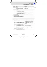
As soon as the key pad is being supplied with voltage, it performs a short self-test.
e
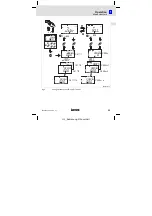
The keypad is ready to operate when it displays the ”Disp” mode:
Current status of the standard device
Parameter set activated via terminal
Display of the inverter’s output frequency
(displayed parameter selectable in C0517/1)
Bar chart display of device’s capacity utilisation
(displayed operating status selectable in C0004)
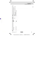
f
Press in order to exit ”Disp” mode


