


Installation
3.2.2
Time chart
n
Q S P
R F R
K
S R
t
Q S P
t 1
t 2
t 3 t 4
t 5
t
A 2
K 4
S 4
t
t
t
t
tt
tt
tt
tt
t 1
t 2
t 3
t 4
t 5
t 6
t
Q S P
" S a f e s t a n d s t i l l "
f u n c t i o n v i a
s t a r t - s t o p m o m e n t a r y
c o n t a c t p u s h b u t t o n
" S a f e s t a n d s t i l l "
f u n c t i o n v i a
" O p e n i n g o f s a f e t y d o o r "
S 2
tt
S 1
tt
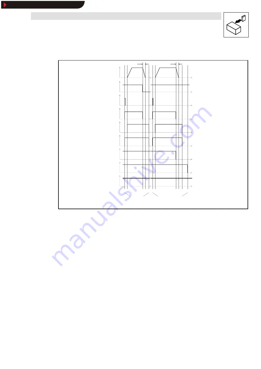
Fig. 4
Time characteristic for switching on and off
“
safety relay and standard PLC control
”
3.2.3
Time settings
•
t1 to t2
≥
50 ms
Set the time delay in the PLC so that the controller will be enabled at least 50 ms after K
SR
.
•
t3 to t4
t
QSP
= Time for controller-internal QSP ramp
The time interval set must ensure that the controller can always be braked to a controlled
standstill when running at max. speed (t3 to t4).
•
t3 to t5 = t
QSP
+ min. 100 ms (standard value)
Set the time (t3 to t5) so that t
QSP
+ min. 100 ms ensures safety.
This ensures a controlled standstill according to stop catergory 1 of EN 60204-1. The
controller will only be enabled again (terminal 28) (t5) once the motor as been braked to a
controlled standstill (t4).
•
t3 to t6 = Internal time of A1, A2 (t
A1
, t
A2
)
t
A1
and t
A2
must be selected to ensure that the controller brakes the motor to a controlled
standstill along the QSP ramp within T
QSP
before the power supply is disconnected via the
mains contactor (K4) (t6). This will be required if
–
the emergency off button (S3) is pressed during operation.
–
the safety door is opened and the feedback contact of K
SR
in the controller is not closed
because of an error in the drive (t6) (2nd switch-off circuit).
Buy: www.ValinOnline.com | Phone 844-385-3099 | Email: [email protected]
Show/Hide Bookmarks