


506305-01
Page 7 of 36
Issue 0938
Preferred fittings are DWV style or long sweep. Seal all joints
gas tight with appropriate cement. In areas where vent and
air intake pipes are exposed to abnormal stress or are subject
to damage, schedule 80 pipe should be used.
Category IV Furnace Limitations
This furnace shall
not
be connected to any Type B, BW, or L
vent or vent connector and shall
not
be connected to any portion
of a factory-built or masonry chimney.
This furnace is not to
be common vented with any other appliance. The vent
pipe must not be connected to a chimney flue serving a
separate appliance designed to burn solid fuel.
Concentric Vent Kit
cement. The cement shall show no gelation, stratification,
or separation that cannot be removed by stirring.
Refer to Table 2 for approved piping and fitting materials.
Canadian Applications Only:
PVC pipe, fittings, primer
and solvent cement used to vent this applicance must be
certified to ULC S636 and supplied by a single manufacturer
as part of an approved venting system. In addition, the first
three feet of vent pipe from the furnace flue collar must be
accessible for inspection. Models that may be installed as a
horizontal furnace include a horizontal drain kit. In Canada
this drain kit must be replaced by a locally available IPEX
Drain Kit # 196014.
For Local IPEX Canadian Customer
Service Center and Kit abailability call IPEX at 1-866-473-
9462.
The primers and solvents used must also meet ASTM
specifications. PVC primer is specified in ASTM F656. Use
PVC solvent as specified in ASTM D2564 and ABS solvent
cement as specified ASTM D2235. Low temperature solvent
cement is recommended. Metal or plastic strapping may
be used for vent pipe hangers.
When making ABS joints, pieces can be prepared with a clean
dry cloth to clean inside socket surface of fitting and male end
of pipe to depth of socket. Refer to procedure specified in
ASTM D3138. When joining ABS to PVC materials, use
transition solvent.
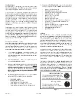
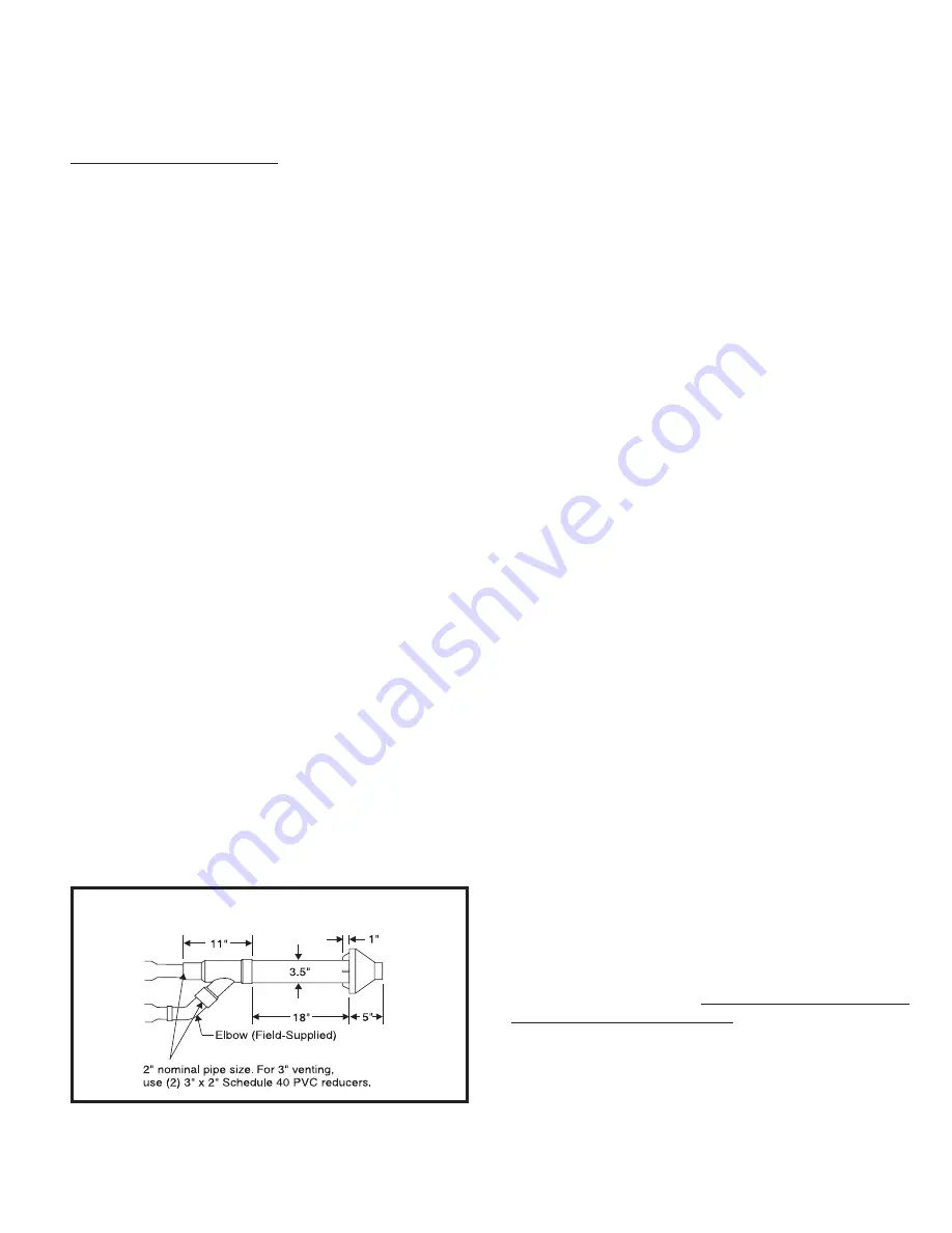
Figure 3
Concentric Vent Kit Dimensions
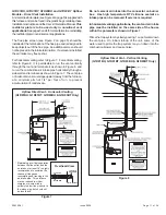
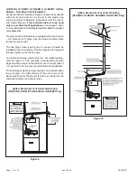
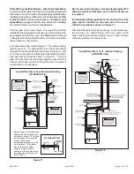
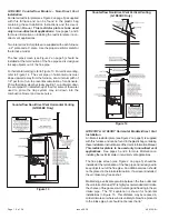
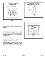
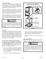
A concentric vent kit (see Accessories section on page 31 for
correct kit) is available for use when installing this furnace as
a direct vent furnace and the air intake and vent pipe are to be
run through the same hole, whether horizontally through the
wall or vertically through the roof (see Figure 3). Refer to the
instructions included with the concentric vent kit for installation
specifics.
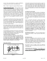
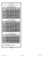
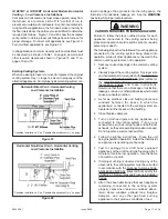
Vent Pipe Size and Length
The vent pipe and air intake pipe (in direct vent installations)
should be sized in accordance with the information found in
the appropriate table in Figure 4. One 90° elbow is equivalent
to 5' of pipe. Two 45° elbows are equivalent to one 90°
elbow. The minimum length certified for use with this furnace
is 5' and one elbow, not including the vent and air intake
terminals.
In the event that the pipe length is in between the lengths
listed in the table, use the next larger length listed. For
example, if a length of pipe needed to install the furnace is
27', use the diameter values for the 30' row in the tables.
For direct vent installations, if the vent and air intake pipe
are not equal in length and number of elbows, then determine
the minimum pipe diameter for both the vent and air intake.
If the results indicate different diameters, use the larger of
the two for both the vent and air intake.
Under no
circumstances should the vent and air intake pipe size
be different in diameter.
For installation details, refer to
the appropriate section in pages 11 – 17 for the unit model
and type of installation.
High Altitude Installation:
2” pipe not recommended at
altitude above 4,000 feet. 3” pipe required for altitude above
5,000 feet.
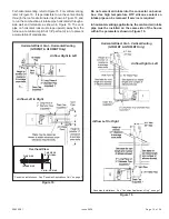
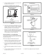
Horizontal Venting
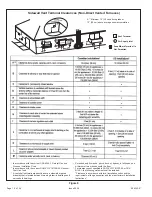
The vent for this appliance shall not terminate over public
walkways; or near soffit vents or crawl space vents or other
areas where condensate or vapor could create a nuisance or
hazard or cause property damage; or where condensate vapor
could cause damage or could be detrimental to the operation
of regulators, relief valves, or other equipment.
See Figures 5 and 6 on pages 9 and 10 for additional
information on where the horizontal vent terminal can and
cannot terminate.
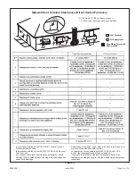
For Massachusetts Installations:
The installation must
comply with Massachusetts 248 CMR 5.08 Modifications to
sections of NFPA-54, Chapter10. (See pages 35 and 36 )