


506305-01
Page 6 of 36
Issue 0938
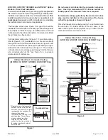
When a furnace is installed as direct vent, provisions for
ventilation air should follow the same requirements as if
installed as non-direct vent. Proper ventilation air is
necessary to maintain furnace component temperatures
within acceptable limits.
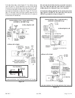
All vents passing through floors, ceilings, and walls must be
installed in accordance with National Fuel Gas Code, ANSI
Z223.1/NFPA 54 (latest edition).
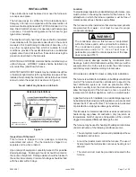
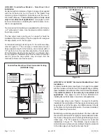
The length of flue pipe exposed to outdoor conditions should
be kept to a minimum. When the installation requires more
than 3 feet of flue pipe be exposed to outdoor conditions,
insulating the exposed flue pipe with 1/2” Armaflex or
equivalent is recommended. In climates with design
temperatures below zero degrees (F), 3/4” Armaflex or
equivalent is recommended.
Materials
All pipe, fittings, primer, and solvent cement must conform
with American National Standard Institute and the American
Society for Testing and Materials (ANSI/ASTM) standards.
The solvent shall be free flowing and contain no lumps,
undissolved particles, or any foreign matter that adversely
affects the joint strength or chemical resistance of the
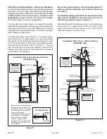
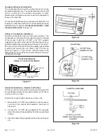
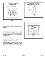
The inlet restrictor plate must be installed in the air inlet in
one of three ways:
•
Restrictor plate in inlet collar: Install the restrictor plate
in the inlet pipe collar in the top panel of the furnace.
Insert a 3" to 36" section of PVC pipe (field supplied)
into the collar. Use high temperature RTV sealant to
attach PVC pipe to collar. A 90° elbow (field supplied)
may be attached to the PVC pipe, but the elbow is not
required. Use high temperature RTV sealant to attach
elbow to PVC pipe (if applicable).
•
Restrictor plate in inlet pipe: Insert a 3" to 36" section of
PVC pipe (field supplied) into the collar. Use high
temperature RTV sealant to attach PVC pipe to collar.
Install the restrictor plate in the end of the inlet pipe just
installed. Attach either a field-supplied coupler or 90°
elbow to the end of the PVC pipe to keep the restrictor
plate in place. Use high temperature RTV sealant to
attach the coupler or elbow to PVC pipe.
•
Restrictor plate in elbow: Insert a 3" to 36" section of
PVC pipe (field supplied) into the collar. Use high
temperature RTV sealant to attach PVC pipe to collar.
Attach a 90° elbow (field supplied) to the PVC pipe. Use
high temperature RTV sealant to attach elbow to PVC pipe.
Install the restrictor plate into the elbow.
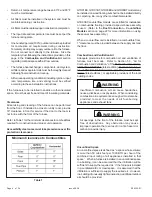
Two different sized inlet restrictor plates are supplied with the
furnace (2" and 3"). Use the proper restrictor plate for the
furnace model.
If at any time in the future the installation of this furnace
is changed to require outside fresh air for combustion,
the inlet air restrictor plate must be removed. Failure to
remove the inlet air restrictor could cause improper
operation that can result in a fire hazard or carbon
monoxide injury.
WARNING
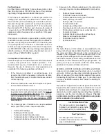
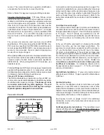
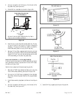
Also included in the plastic bag containing the inlet air
restriction plate is a flue pipe screen (see Figure 2). In all
installations, this screen sould be installed at the termination
of the flue pipe and is designed to keep objects out of the
flue pipe.
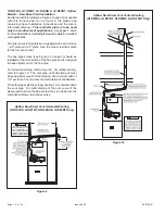
For either type of installation (direct or non-direct vent),
special venting considerations must be followed. Refer to
the proper section in pages 11 – 17 for the type of furnace
and venting being installed.
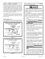
The venting system must be supported with mounting straps
to prevent any weight load from being applied to the vent
blower. Horizontal vent pipe must be supported every 5'
and vertical pipe should be supported every 10' to prevent
sagging and provide rigid support.
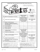
Table 2
Piping and Fitting Specifications
Piping & Fitting
Material
ASTM
Specification
Schedule 40 PVC
(Pipe)
D1785
Schedule 40 PVC
(Cellular Core Pipe)
F891
Schedule 40 PVC
(Fittings)
D2466
SDR-26 CPVC
(Pipe)
D2241
Schedule 40 ABS
(Pipe)
D1527
Schedule 40 ABS
(Fittings)
D2468
Schedule 40 & 80 CPVC
(Pipe)
F441
ABS-DWV
Drain Waste & Vent
(Pipe & Fittings)
D2661
PVC-DWV
Drain Waste & Vent
(Pipe & Fittings)
D2665
F442
SDR-26
(Pipe)
Schedule 40 ABS
Cellular Core
DWV (Pipe)
F628
F438
Schedule 40 & 80 CPVC
(Fittings)