


506305-01
Page 14 of 36
Issue 0938
G1D93BC Counterflow Models – Non-Direct Vent
Installation
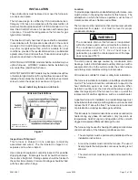
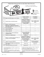
An inlet air restrictor plate (see Figure 2 on page 5) is supplied
with this furnace and can be found in the plastic bag
containing these Installation Instructions and the User’s
Information Manual.
This restrictor plate is to be used
only in non-direct vent applications.
See pages 5 and 6
for more information on installing the restrictor plate in non-
direct vent applications.
Two inlet air restrictor plates are supplied with each furnace
- a 2” plate and a 3” plate. Use the proper restrictor plate for
the furnace model.
The flue pipe screen (see Figure 2 on page 5) should be
installed at the termination of the flue pipe and is designed
to keep objects out of the flue pipe.
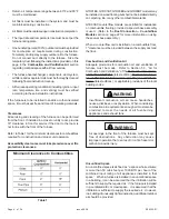
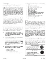
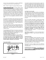
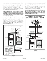
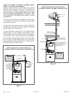
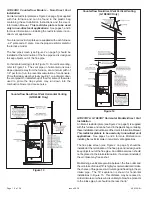
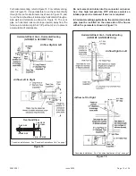
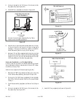
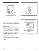
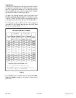
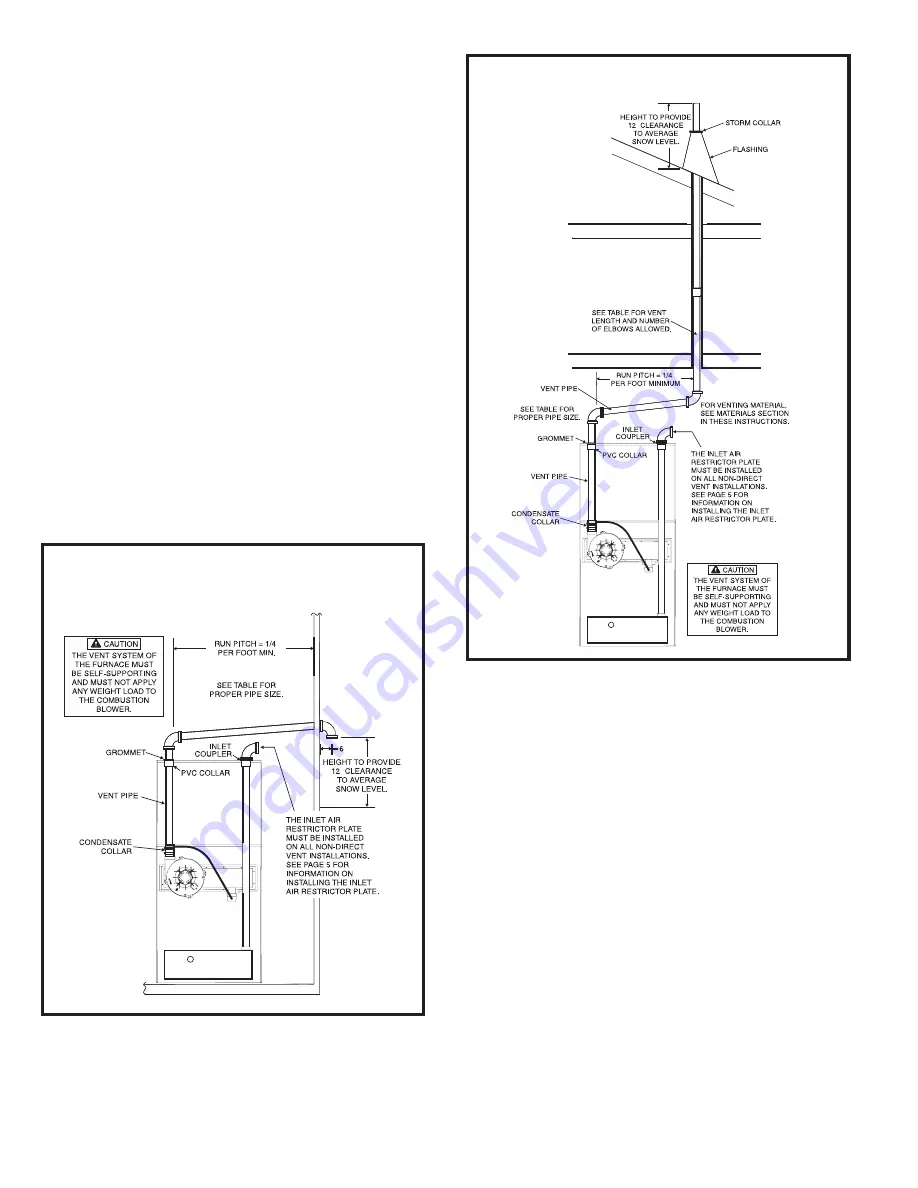
For horizontal venting, refer to Figure 13. For vertical venting,
refer to Figure 14. The vent pipe on horizontal runs must
slope upward, away from the furnace, at a minimum pitch of
1/4" per foot of run, to prevent accumulation of condensate.
Prime the trap system by slowly pouring 1 cup of water down
the vent pipe. On initial start-up of the unit, some of the water
used to prime the trap system may run down into the
combustion blower and cause noise.
G1D91BT & G1D93BT Horizontal Models-Direct Vent
Installation
An inlet air restrictor plate (see Figure 2 on page 5) is supplied
with this furnace and can be found in the plastic bag containing
these Installation Instructions and the User’s Information Manual.
This restrictor plate is to be used only in non-direct vent
applications.
See pages 5 and 6 for more information on
installing the restrictor plate in non-direct vent applications.
The flue pipe screen (see Figure 2 on page 5) should be
installed at the termination of the flue pipe and is designed to
keep objects out of the flue pipe. An additional screen should
not be placed in the intake termination. If a screen is installed,
the air intake may freeze shut.
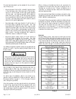
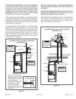
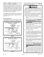
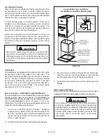
Maintaining a vertical separation between the flue outlet and
the air intake of at least 18” is highly recommended to minimize
the chance of flue gasses re-circulating and freezing in the air
intake pipe. The 18” separation is shown for horizontal
installations in Figure 15. This distance may be reduced in
milder climates or where wind is unlikely to blow flue products
to the intake pipe, but should not be less than 6”.
Figure 13
Counterflow Non-Direct Vent Horizontal Venting
(G1D93BC Only)
(CL
O
SE
D)
DRA
N
H
O
L
E
THRU.
59.69/
56.64
"
"
"
Figure 14
Counterflow Non-Direct Vent Vertical Venting
(G1D93BC Only)
"
(CL
O
SE
D)
DRAI
N
H
O
L
E
TH
RU.
59.69/
56.64
"