background image

Page 18

H- Proper Ground and Voltage

A poorly grounded furnace can contribute to premature ig­
nitor failure. Use the following procedure to check for
ground and voltage to the integrated control.
 1 - Measure the AC voltage between Line Neutral (spade

terminals) and “C” terminal (low voltage terminal
block) on the integrated control. See figure 15. A wide
variation in the voltage between Line Neutral and “C”
as a function of load indicates a poor or partial ground.
Compare the readings to the table below. If the read­
ings exceed the maximum shown in table 11, make re­
pairs before operating the furnace.

 2 - In addition, measure the AC voltage from Line Hot to

Line Neutral (spade terminals) on the integrated con­
trol. See figure 16. This voltage should be in the range
of 204 to 264VAC. 

TABLE 11

Furnace Status

Measurement VAC

Expected

Maximum

Power On Furnace Idle

0.3

2

CAI / Ignitor Energized

0.75

5

Indoor Blower Energized

Less than 2

10

AN2

GREEN

AN1

RED

CHECK VOLTAGE BETWEEN LINE NEUTRAL

AND LOW VOLTAGE “C” TERMINAL

FIGURE 15

FIGURE 16

AN2

GREEN

AN1

RED

CHECK VOLTAGE BETWEEN LINE HOT

AND LINE NEUTRAL

Summary of Contents for ML180UH070AP36A

Page 1: ...ocedures outlined in this manual except where noted are recommended only and do not constitute code WARNING This product contains a chemical known to the State of California to cause cancer birth defects or other reproductive harm TABLE OF CONTENTS Specifications Page 2 Blower Data Page 3 Parts Identification Page 5 I Unit Components Page 6 II Installation Page 14 III Start Up Page 14 IV Heating S...

Page 2: ...Mj h 116 1 139 3 Output kW 25 8 31 0 Temperature rise range C 17 33 17 33 Gas Manifold Pressure kPa Natural Gas Propane 0 87 2 30 0 87 2 30 High Static Pa 125 125 Connections Flue connection mm round 102 102 Gas pipe size IPS 1 2 in 1 2 in Indoor Blower Wheel nom diameter x width mm 292 x 254 279 x 279 Motor output W 746 746 Add on cooling kW 14 1 17 6 14 1 17 6 Air Volume Range L s 633 1138 602 1...

Page 3: ...3 577 386 481 50 849 1016 679 831 460 565 384 464 75 831 967 676 807 456 546 369 447 100 827 937 667 773 452 526 364 434 125 816 906 660 747 439 509 349 421 150 799 872 647 718 426 494 331 408 175 784 845 629 691 411 477 308 394 200 754 808 601 642 394 460 290 383 225 722 765 577 622 359 435 256 363 250 674 713 555 593 332 421 229 348 ML180UH110AP36C PERFORMANCE Less Filter External Static Pressur...

Page 4: ...835 974 696 800 956 1192 801 966 678 808 250 947 1140 807 943 677 775 939 1158 789 955 665 786 ML180UH135AP60D PERFORMANCE Less Filter External Static Pressure Pa Air Volume at Different Blower Speeds Bottom Return Air Side Return Air with Optional Return Air Base Return Air from Both Sides or Return Air from Bottom and One Side Single Side Return Air Air volumes in bold require field fabricated t...

Page 5: ...nger Pressure Switch Burner Manifold Assembly Gas Valve IEC Receptacle Blower Assembly Transformer Capacitor Blower Access Panel Upper Access Panel Control Box Limit Switch under combustion air inducer Shipping Pad ML180UH090AP48B ML180UH110AP36C only Remove prior to operation ...

Page 6: ... trip and all unit opera tion will shutdown The breaker can be manually reset by pressing the button on the face See figure 3 FIGURE 3 CIRCUIT BREAKER CB8 PRESS TO RESET 4 Integrated Control A92 WARNING Shock hazard Disconnect power before servicing Control is not field repairable If control is inoperable simply re place entire control Can cause injury or death Unsafe operation will re sult if rep...

Page 7: ...als 230VAC HEAT Heating Speed 230VAC FS Flame Sense LED red TABLE 1 5 Pin Terminal Designation PIN FUNCTION 1 Ignitor Line 2 Not Used 3 Combustion Air Inducer Low 4 Combustion Air Inducer Neutral 5 Ignitor Neutral TABLE 2 12 Pin Terminal Designations PIN FUNCTION 1 Not Used 2 Not Used 3 Rollout Switch Input 4 Ground 5 TH 24V Hot 6 High Limit Input 7 Gas Valve Line 8 Gas Valve Common 9 TR 24V Retur...

Page 8: ...r of retries Burners failed to light 4 2 Watchguard Exceeded maximum number of retries or last retry was due to pressure switch opening 4 3 Watchguard Exceeded maximum number of retries or last retry was due to flame failure 4 5 Watchguard Limit remained open longer than three minutes 4 6 Watchguard Flame sensed out of sequence flame signal gone 4 8 Low line voltage HARD LOCKOUT CODES 5 1 Hard loc...

Page 9: ...tion sequence again The integrated control has an added feature of ignitor pow er regulation to maintain consistent lighting and longer igni tor life under all line voltage conditions Fan Time Control Heating Fan On Time The fan on time of 30 seconds is not adjustable Heating Fan Off Time Fan off time time that the blower operates after the heat demand has been satisfied can be adjusted by moving ...

Page 10: ...e inte grated control immediately stops ignition and closes the gas valve If unit is running and flame rollout is detected the gas valve will close and integrated control will be disabled Rollout can be caused by a blocked heat exchanger flue or lack of combustion air The switch has a factory setpoint of 99 C 210 F and cannot be adjusted To manually reset a tripped switch push the reset button loc...

Page 11: ...ake sure that the furnace is wired correctly and is properly grounded FIGURE 7 Test 1 Remove 5 pin plug from control Insert test pins from meter into plug pin 1 and 5 If reading is correct test is over If reading is outside ac ceptable range move to test 2 Test 2 Separate the 2 pin jack plug and again check resistance to the ignitor If reading is acceptable then the problem is the wiring be tween ...

Page 12: ...TABLE 4 ML180UHA Unit C A I Orifice Size mm in 070AP36A 35 7 1 406 090AP48B 42 2 1 660 110A36C 110AP60C 47 6 1 875 135AP60D 55 6 2 188 11 Combustion Air Inducer Pressure Switch S18 ML180UHA series units are equipped with a combustion air pressure switch located on the combustion air inducer ori fice bracket The switch is connected to the combustion air inducer housing by means of a flexible silico...

Page 13: ...inducer then reinstall the mounting screws See unit Installation In structions for more detail IMPORTANT The combustion air pressure switch must be moved for horizontal discharge air left position FIGURE 8 vent pipe vent pipe flue transition vent pipe FLOW AIR flue transition vent pipe pressure switch vent pipe In all positions route the wires away from moving parts and the heat of the inducer mot...

Page 14: ...T FIGURE 11 Set Screw Housing Hub ALIGN AND TIGHTEN SET SCREW WITH FLAT SIDE OF MOTOR SHAFT Motor Shaft NOTE The 5 ton blower will have two flats and two set screws 90 of each other 13 Secondary Limit Controls The secondary limit is located in the blower compartment in the back side of the blower housing See figure 9 When ex cess heat is sensed in the blower compartment the limit will open If the ...

Page 15: ...cess panels and covers must be in place and se cured IV HEATING SYSTEM SERVICE CHECKS A Certification All units are Australian Gas Installation Code AS NZS5601 certified Refer to the ML180UHA Installation In struction B Gas Piping Gas supply piping should not allow more than 125Pa 13 mm W C drop in pressure between gas meter and unit Supply gas pipe must not be smaller than unit gas connec tion Co...

Page 16: ...or gas leaks Seal any leaks if found E Proper Combustion Furnace should operate a minimum 15 minutes with cor rect manifold pressure and gas flow rate before checking combustion Take combustion sample beyond the flue out let and compare to the tables below The maximum carbon monoxide reading should not exceed 100 ppm TABLE 7 ML180UHA Unit CO2 For Nat CO2 For L P 070 6 3 7 8 7 0 9 0 090 110 135 F H...

Page 17: ...tegrated control flame sensor wire from the flame sensor 4 Connect lead to flame sensor 5 Connect lead to the ignition control sensor wire 6 Turn supply voltage on and close thermostat contacts to cycle system 7 When main burners are in operation for two minutes take reading TABLE 10 Flame Signal in Microamps Normal Low Drop Out 1 5 0 5 1 4 0 4 FIGURE 14 Measuring Flame Signal Flame Sensor Flame S...

Page 18: ...ial ground Compare the readings to the table below If the read ings exceed the maximum shown in table 11 make re pairs before operating the furnace 2 In addition measure the AC voltage from Line Hot to Line Neutral spade terminals on the integrated con trol See figure 16 This voltage should be in the range of 204 to 264VAC TABLE 11 Furnace Status Measurement VAC Expected Maximum Power On Furnace I...

Page 19: ... re turn air plenums Insert manometer hose flush with in side edge of hole or insulation Seal around the hose with permagum Connect the zero end of the manome ter to the discharge supply side of the system On ducted systems connect the other end of manometer to the return duct as above 3 With only the blower motor running and the evaporator coil dry observe the manometer reading Adjust blow er mot...

Page 20: ...ed behind the combus tion air inducer Be careful with the collector box gas ket If the gasket is damaged it must be replaced to prevent leakage 6 Disconnect gas supply piping Remove the screw se curing the burner box cover and remove cover Re move the four screws securing the burner manifold as sembly to the vestibule panel and remove the assem bly from the unit 7 Remove screws securing burner box...

Page 21: ...ed on the Lennox ML180UHA series units are permanently lubricated and need no further lu brication D Flue and Chimney Flue must conform to local codes Flue pipe deteriorates from the inside out and must be disconnected in order to check thoroughly Check flue pipe chimney and all con nections for tightness and to make sure there is no block age or leaks E Electrical 1 Check all wiring for loose con...

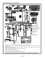
Page 22: ...on air pressure switch closes Once it closes a 15 second pre purge follows 4 Integrated control A92 energizes ignitor A 20 second warm up period begins 5 Gas valve opens for a 4 second trial for ignition 6 Flame is sensed gas valve remains open for the heat call 7 After 45 second delay integrated control A92 energizes indoor blower B3 8 When heat demand is satisfied W1 of the indoor thermostat de ...

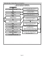
Page 23: ...OSED YES NO COMBUSTION AIR INDUCER OFF INDOOR BLOWER ON HAS PRIMARY OR SECONDARY LIMIT RESET WITHIN 3 MINUTES STATUS ERROR CODE 3 1 ROLLOUT SWITCH CLOSED GAS VALVE OFF COMBUSTION AIR INDUCER ON INDOOR BLOWER ON STATUS ERROR CODE 5 1 SEQUENCE HOLDS UNTIL ROLLOUT SWITCH IS RESET AND MAIN POWER IS INTERRUPTED OR T STAT IS CYCLED OFF ON FOR 3 SEC MINIMUM NO YES PRESSURE SWITCH CONTACTS OPEN NO GAS VAL...

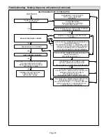
Page 24: ...ATCHGUARD MODE STATUS ERROR CODE 4 7 YES AT END OF IGNITOR 20 SECOND WARM UP PERIOD 4 SECOND TRIAL FOR IGNITION GAS VALVE OPENS IGNITOR ENERGIZED DURING 4 SECOND TRIAL UNTIL FLAME SENSED YES 4 SECOND FLAME STABILIZATION PERIOD FLAME RECTIFICATION CURRENT CHECK CAN FLAME BE PROVEN WITHIN 4 SECONDS AFTER GAS VALVE OPENS u0 20 microamps GAS VALVE OFF COMBUSTION AIR INDUCER ON INDOOR BLOWER OFF STATUS...

Page 25: ...ER OFF INDOOR BLOWER OFF WITH DELAY STATUS ERROR CODE 4 5 IS 60 MINUTE RESET PERIOD COMPLETE THERMOSTAT CALLS FOR HEAT STATUS LED HEARTBEAT SEE BOX A NO YES GAS VALVE OFF COMBUSTION AIR INDUCER ON INDOOR BLOWER OFF AFTER DELAY STATUS ERROR CODE 2 3 CONTROL RESTARTS IGNITION SEQUENCE IF PRESSURE SWITCH CLOSES WITHIN 2 1 2 MINUTES NO YES HEAT DEMAND SATISFIED GAS VALVE OFF COMBUSTION AIR INDUCER OFF...

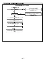
Page 26: ... POLARITY REVERSED THERMOSTAT CALLS FOR COOL COMPRESSOR AND CONDENSER FAN ENERGIZED NO IS THERE PROPER GROUND YES NO INDOOR BLOWER ENERGIZED ON COOL SPEED AFTER 2 SECOND DELAY DEMAND FOR COOL SATISFIED COMPRESSOR AND CONDENSER FAN DE ENERGIZED INDOOR BLOWER DE ENERGIZED AFTER 45 SECOND DELAY YES SIGNAL IMPROPER GROUND AT LED CONTROL WILL CONTINUE TO CALL FOR COOLING IN THIS CONDITION STATUS ERROR ...

Page 27: ...FOR HEAT W THERMOSTAT CALLS FOR COOLING THERMOSTAT OPENS SYSTEM FAN SWITCHED TO COOL SPEED EAC TERM REMAINS ON THERMOSTAT OPENS MANUAL FAN SELECTION MADE AT THERMOSTAT CONTROL G ENERGIZES SYSTEM FAN AT HEAT SPEED EAC TERM ENERGIZED NO YES YES NO HUM TERM ENERGIZES WITH COMB AIR INDUCER SYSTEM FAN REMAINS ON HEATING SPEED SYSTEM FAN REMAINS ON HEATING SPEED HUM TERM DE ENERGIZES WITH COMB AIR INDUC...

Reviews: