


Page 17
G- Flame Signal
A microamp DC meter is needed to check the flame signal
on the integrated control.
Flame (microamp) signal is an electrical current which passes
from the integrated control to the sensor during unit operation.
Current passes from the sensor through the flame to ground to
complete a safety circuit.
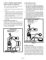
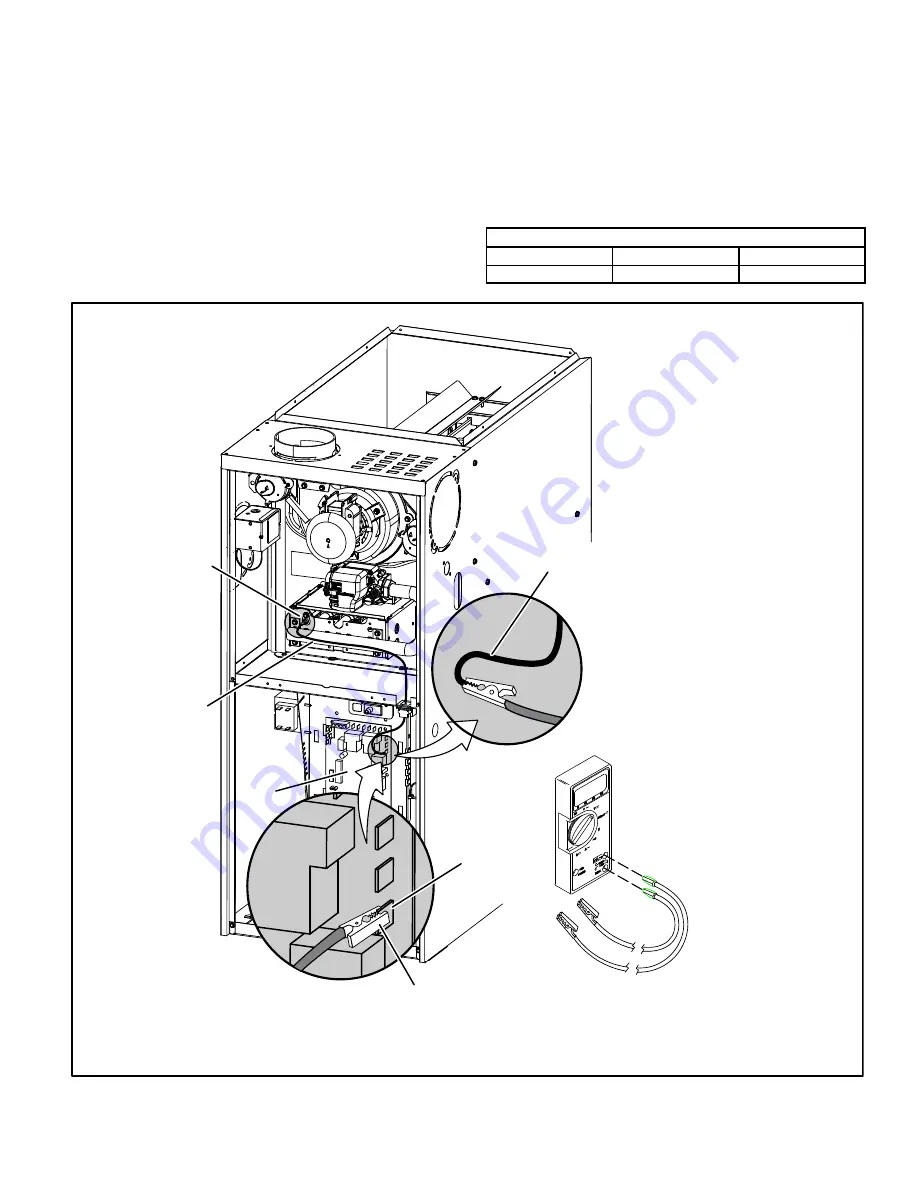
To Measure Flame Signal - Integrated Control:
Use a digital readout meter capable of reading DC micro
amps. See figure 14 and table 10 for flame signal check.
1 - Set the meter to the DC amps scale.
2 - Turn off supply voltage to control.
3 - Disconnect integrated control flame sensor wire from
the flame sensor.
4 - Connect (-) lead to flame sensor.
5 - Connect (+) lead to the ignition control sensor wire.
6 - Turn supply voltage on and close thermostat contacts to
cycle system.
7 - When main burners are in operation for two minutes, take
reading.
TABLE 10
Flame Signal in Microamps
Normal
Low
Drop Out
1.5
0.5 - 1.4
0.4
FIGURE 14
Measuring Flame Signal
Flame
Sensor
Flame Sensor
Wire
Integrated
Control
Remove Sensor Wire from
Integrated Control and
Connect Alligator Clip (
−
)
to Frame Sensor Lead
Flame Sensor
Terminal
Remove Sensor Wire from
Integrated Control and
Connect Alligator Clip (+)
to Terminal on Control
(+)
DIGITAL METER
(+) To Control
Sensor
Terminal
(-) To
flame
sensor
Set dial to measure dc microamps
(+)
Red Collar
Indicates
Positive Leads


