background image

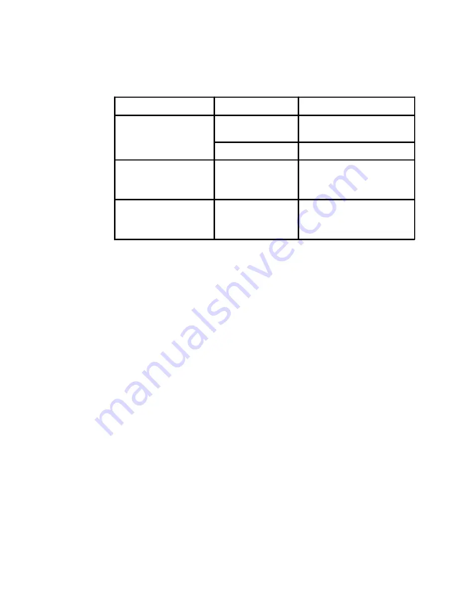
Table 3-1. Monitor specifications for type-model 5047-HC2 (continued)

3-2

LT1712p  Flat  Panel  Monitor  User

s  Guide

Communications

VESA DDC

CI

Supported Display Modes

(VESA Standard modes

between noted ranges)

Horizontal frequency
Vertical frequency

30 kHz - 83 kHz
50 Hz - 75 Hz

Native Resolution

1280 x 1024 at 60 Hz

Temperature

Operating
Storage
Shipping

0

0

 to 40

0

 C (32

0

 to 104

0

 F)

-20

to 60

0

 C (-4

to 140

0

 F)

-20

to 60

0

 C (-4

0

 to 140

0

 F)

Humidity

Operating
Storage
Shipping

8% to 80%
5% to 95%
5% to 95%

Summary of Contents for ThinkVision LT1712p

Page 1: ...LT1712p Flat Panel Monitor User s Guide ...

Page 2: ...expense and are sold to governmental entities as commercial items as defined by 48 C F R 2 101 with limited and restricted rights to use reproduction and disclosure LIMITEDANDRESTRICTED RIGHTS NOTICE If products data computer software or services are delivered pursuant a General ServicesAdministration GSA contract use reproduction or disclosure is subject to restrictions set forth in Contract No G...

Page 3: ...2 Accessibility information 2 3 Adjusting your monitor image 2 3 Using the direct access controls 2 3 Using the On Screen Display OSD controls 2 3 Selecting a supported display mode 2 6 Understanding power management 2 7 Caring for your monitor 2 8 Detaching the monitor stand 2 9 Wall Mounting Optional 2 9 Chapter 3 Reference information 3 1 Monitor specifications 3 1 Troubleshooting 3 3 Manual im...

Page 4: ...Safety information Copyright Lenovo 2012 iii General Safety guidelines For tips to help you use your computer safety go to http www lenovo com safety ...

Page 5: ...bleshooting and Warranty Guide Reference and Driver CD ThinkVision LT1712p Flat Panel Monitor Power Cord Analog Signal Cable Attached to monitor Digital Signal Cable Attaching the base and handling your monitor To set up your monitor please see the illustrations below Note Do not touch the monitor within the screen area The screen area is glass and can be damaged by rough handling or excessive pre...

Page 6: ...ation on adjusting monitor positions setting user controls and using the cable lock slot Types of adjustments Tilt Please see the illustration below for an example of the tilt range Height Adjustment After pressing the top of the monitor remove the fixed pin and adjust the height of the monitor ...

Page 7: ... the base metal plate 3 Tighten the quick release screw with L bracket Fix U chip on the L bracket Chapter 1 Getting started 1 3 1 Press the monitor head and remove the fixed chip and main clip Lift the monitor head to the highest location Insert L bracket lenovo concerned option function ...

Page 8: ... lower left corner Please follow the instructions that came with the cable lock to attach it Setting up your monitor This section provides information to help you set up your monitor Connecting and turning on your monitor Note Be sure to read the Safety Information located in the Monitor Safety Troubleshooting and Warranty Guide before carrying out this procedure 1 Power off your computer and all ...

Page 9: ...eo port on the back of the computer Note One end of the signal cable is already pre attached to your monitor Connect the digital cable to the DVI connector of the monitor and the other end on the back of the computer Chapter 1 Getting started 1 5 ...

Page 10: ...ulations shall be considered A certified power supply cord not lighter than ordinary polyvinyl chloride flexible cord according to IEC 60227 designationH05VV F3G 0 75mm2 orH05VVH2 F2 3G 0 75mm2 shall be used Alternative a flexible cord be of synthetic rubber according to IEC 60245 designation H05RR F 3G 0 75mm2 shall be used Place the cables through the Main Clip 1 6 LT1712p Flat Panel Monitor Use...

Page 11: ... monitor image if using the analog cable press the Automatic Image Setup key Automatic image setup requires that the monitor is warmed up for at least 15 minutes This is not required if you are using the DVI cable Note If automatic image setup does not establish the image that you prefer perform manual image setup See Manual image setup on page 3 4 Chapter 1 Getting started 1 7 ...

Page 12: ...luable to us in developing products and services that are important to you as well as in developing better ways to communicate with you Register your option on the followingWeb site http www lenovo com register Lenovo will send you information and updates on your registered product unless you indicate on the Web site questionnaire that you do not want to receive further information 1 8 LT1712p Fla...

Page 13: ...llowing topics describe how to optimize equipment setup to achieve and maintain good working posture Positioning and viewing your monitor Position and adjust your computer monitor for comfortable viewing by considering the following items Viewing distance Optimal viewing distances for monitors range from approximately 510mm to 760mm 20 in to 30 in and can vary depending on ambient light and time o...

Page 14: ...he setup of your computer equipment have a large effect on your posture while using your computer Be sure to optimize the position and orientation of your equipment by following the tips outlined in Arranging your work area on page 2 1 so you can maintain a comfortable and productive posture Also be sure to use the adjustment capabilities of your computer components and office furniture to best su...

Page 15: ...itor image This section describes the user control features used to adjust your monitor image Using the direct access controls The direct access controls can be used when the On Screen Display OSD is not displayed Table 2 1 Direct access controls Icon Control Description Image Setup Activates automatic image adjustment Brightness Direct access to Brightness adjustment Input Change Switches the vid...

Page 16: ... Press to move backwards through the sub menus and exit from the OSD 4 Press and hold for 10 seconds to lock the OSD This will prevent accidental adjustments to the OSD Press and hold for 10 seconds to unlock the OSD and allow adjustments to the OSD 5 Enables DDC CI by default Use OSD Exit Key Press and hold the button for 10 seconds to disable enable DDC CI function The words DDC CI Disable or DD...

Page 17: ...ustom Red Increases or decreases the saturation of red in the image Green Increases or decreases the saturation of green in the image Blue Increases or decreases the saturation of blue in the image Save Saves the custom color choices Input Signal This monitor can accept video signals through two different connectors Most desktop computers use a D SUB connector Select digital among OSD Controls whe...

Page 18: ... Table 2 2 OSD functions continued Selecting a supported display mode The display mode the monitor uses is controlled by the computer Therefore refer to your computer documentation for details on how to change display modes The image size position and shape might change when the display mode changes This is normal and the image can be readjusted using automatic image setup and the image controls U...

Page 19: ...e are several states as described in the table below For optimal performance switch off your monitor at the end of each working day or whenever you expect to leave it unused for long periods during the day Table 2 4 Power indicator 2 7 LT1712p Flat Panel Monitor User s Guide State Power Indicator Screen Restoring Operation Compliance On Steady green Normal Standby Suspend Steady amber Blank Press ...

Page 20: ...reen area Do Lightly dampen a soft cloth with water and use this to gently wipe the covers and the screen Remove grease or finger marks with a damp cloth and a little mild detergent Chapter 2 Adjusting and using your monitor 2 8 DPS Dynamic Power saving function caring If you find slightly change of brightness on your monitor please don t worry that s because the DPS Dynamic Power saving is enable...

Page 21: ...patible base mounting kit 1 Place the monitor face down on a non abrasive surface on stable flat table 2 Remove the stand 3 Attach the mounting bracket from the wall mounting kit to the monitor 4 Mount the monitor on the wall by following the instructions that come with the base mounting kit NOTE For use only with UL expand UL Listed Wall Mount Bracket with minimum weight load bearing capacity of ...

Page 22: ...itch 430 mm 17 in 270 34 mm 10 60 in 337 92 mm 13 30 in 0 264 mm 010 in V Power input Supply voltage Max supply current 100 240 V AC 50 60 Hz 1 5 A Power consumption Note Power consumption figures are for the monitor and the power supply combined Normal operation Standby Suspend Off 18 W 0 5 W Analog and Digital 0 5 W Video input Analog Input signal Horizontal addressability Vertical addressabilit...

Page 23: ...ported Display Modes VESA Standard modes between noted ranges Horizontal frequency Vertical frequency 30 kHz 83 kHz 50 Hz 75 Hz Native Resolution 1280 x 1024 at 60 Hz Temperature Operating Storage Shipping 00 to 400 C 320 to 1040 F 200 to 600 C 40 to 1400 F 200 to 600 C 40 to 1400 F Humidity Operating Storage Shipping 8 to 80 5 to 95 5 to 95 ...

Page 24: ...cting and turning on your monitor on Page 1 4 The color settings may be incorrect Select another color setting from the OSD menu Adjusting your monitor image on page 2 3 The automatic image setup function was not performed Perform automatic image setup Adjusting your monitor image on page 2 3 The power indicator is not lit and there is no image The monitors power switch is not switched on The powe...

Page 25: ...s and contrast are at the lowest setting Adjust the brightness and contrast setting on the OSD menu Adjusting your monitor image on page 2 3 One or more of the pixels appear discolored This is a characteristic of the LCD technology and is not an LCD defect If there are more than five pixels missing contact the Lenovo Support Center Appendix A Service and Support on page A 1 Fuzzy lines in text or ...

Page 26: ...connected correctly 3 Turn on the monitor and then the system unit Allow the system to boot into Windows Vista operating system 4 Click Start Control Panel and then click the Hardware and Sound icon 5 Click the Personalization icon 6 Click the Display Settings icon 7 Click the Advanced Settings button 8 Click the Monitor tab 9 Click the Properties button 10 If the Windows needs your permission to ...

Page 27: ... tab 8 Click the Properties button 9 Click the Drivers tab 10 Open the Hardware Update Wizard window by clicking on the Update Driver If appears Can Windows connect to Windows Update window please select No not this time option and then click Next 11 Select Install from a list or Specific location Advanced and then click Next 12 Select Don t search I will choose the driver to install option and th...

Page 28: ...rs tab 9 Click the Update Driver 10 Select Browse my computer for driver software option 11 Click on the Browse button and navigate to the following directory X Monitor Drivers where X is the drive letter designator for the CD ROM drive 12 Select the LT1712p inf file and click the Open button Click on the OK button 13 Select Lenovo LT1712p and click Next The files will be copied from the CD to you...

Page 29: ...low Customer responsibilities The warranty does not apply to a product which has been damaged due to accident misuse abuse improper installation usage not in accordance with product specifications and instructions natural or personal disaster or unauthorized alterations repairs or modifications The following are examples of misuse or abuse and not covered by warranty Images burned onto the screen ...

Page 30: ...ws information for model 5047 HC2 Table 3 3 List of service parts Chapter 3 Reference information 3 9 FRU Field Replaceable Unit Part number Description Color Machine Type Model MTM 03X7959 Monitor_LT1712p Business Black 5047 HC2 57Y2301 Signal cable Analog Business Black 5047 HC2 57Y2302 Signal cable Digital Business Black 5047 HC2 03X7960 Stand Base Business Black 5047 HC2 ...

Page 31: ...ative can help you determine the best alternative Telephone technical support Installation and configuration support through the Customer Support Center will be available until 90 days after the option has been withdrawn from marketing After that time the support is cancelled or made available for a fee at Lenovo s discretion Additional support is also available for a nominal fee Before contacting...

Page 32: ...hasa Melayu Canada Toronto 416 383 3344 Outside Toronto 1 800 565 3344 English French Chile Toll Free 188 800 442 488 800 361 213 Spanish China 86 10 58851110 800 990 8888 Mandarin China Hong Kong S A R ThinkCentre Commercial PC 8205 0333 Multimedia Home PC 800 938 228 Cantonese English Mandarin China Macau S A R ThinkCentre Commercial PC 795 9892 Multimedia Home PC 0800 336 Cantonese English Mand...

Page 33: ...Hungarian India 1800 425 2666 91 80 2535 9182 English Indonesia 021 5238 823 Local number only 001 803 606 282 DID Direct Inward Dialing 603 8315 6859 English Bahasa Indonesia Ireland Warranty service and support 01 881 1444 English Israel Givat Shmuel Service Center 972 3 531 3900 Hebrew English Italy Warranty service and support 39 800 820094 Italian Japan Toll Free 0120 20 5550 International 81...

Page 34: ...800 220 1830 Spanish Norway Warranty service and support 8152 1550 Norwegian Panama Lenovo Customer Support Center 001 866 434 2080 Toll Free 206 6047 Spanish Peru 0 800 50 866 Spanish Philippines 1800 1601 0033 English Filipino Poland 48 22 878 6999 Polski Portugal 351 21 892 7046 Portuguese Romania 4 021 224 4015 Russia Moscow 7 495 258 6300 Toll Free 8 800 200 6300 Russian Singapore Local numbe...

Page 35: ...number only 1 800 060 066 66 2273 4088 DID 603 8315 6857 Thai English Turkey 00800 4463 2041 Turkish United Kingdom Standard warranty support 08705 500 900 English United States 1 800 426 7378 English Uruguay 000 411 005 6649 Spanish Venezuela 0 800 100 2011 Spanish Vietnam For Northern Area and Hanoi City 844 3 946 2000 or 844 3 942 6457 For Southern Area and Ho Chi Minh City 848 3 829 5160 or 84...

Page 36: ... INFRINGEMENT MERCHANTABILITYOR FITNESS FORAPARTICULAR PURPOSE Some jurisdictions do not allowdisclaimer of express or implied warranties in certain transactions therefore this statement may not apply to you This information could include technical inaccuracies or typographical errors Changes are periodically made to the information herein these changes will be incorporated in new editions of the ...

Page 37: ... Actual results may vary Users of this document should verify the applicable data for their specific environment Recycling information Lenovo encourages owners of information technology IT equipment to responsibly recycle their equipment when it is no longer needed Lenovo offers a variety of programs and services to assist equipment owners in recycling their IT products For information on recyclin...

Page 38: ...arge for home used computers sold after October 1 2003 For details visit the Lenovo Web site at www ibm com jp pc service recycle personal Disposing of Lenovo computer components Some Lenovo computer products sold in Japan may have components that contain heavy metals or other environmental sensitive substances To properly dispose of disused components such as a printed circuit board or drive use ...

Page 39: ...iğine Uygunluk Beyanı Bu Lenovo ürünü T C Çevre ve Orman Bakanlığı nın Elektrik ve Elektronik Eşyalarda Bazı Zararlı Maddelerin Kullanımının Sınırlandırılmasına Dair Yönetmelik EEE direktiflerine uygundur EEE Yönetmeliğine Uygundur Lenovo and the Lenovo logo are trademarks of Lenovo in the United States other countries or both Ukraine RoHS Цим підтверджуємо що продукція Леново відповідає вимогам н...

Reviews: