144 Module removal and replacement
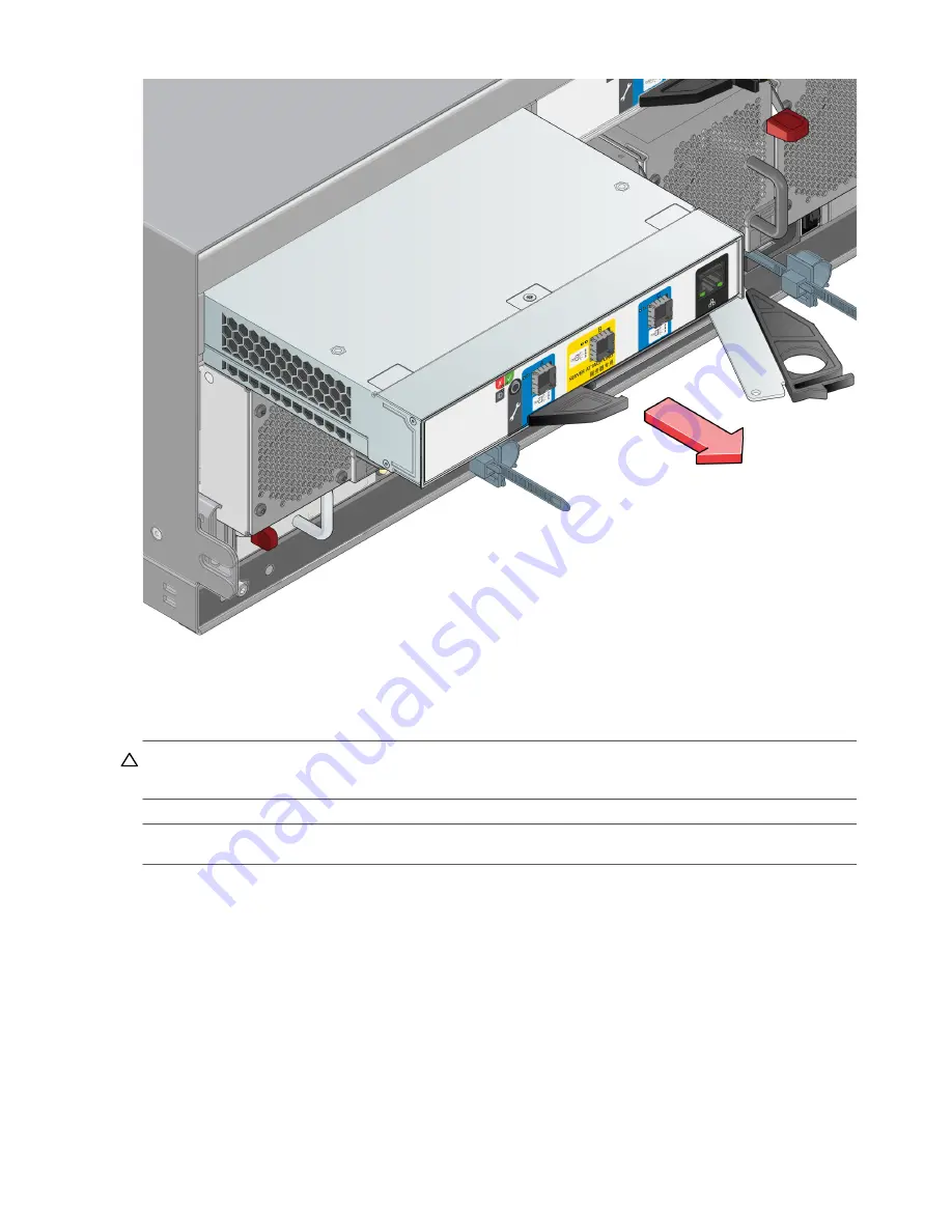
Figure 104 Removing an IOM (2 of 2)
Installing an IOM
See CAUTION bullets regarding
electrostatic discharge
and
anti-static protection
.
CAUTION:
If passive copper cables are connected, the cable must not have a connection to a common ground/earth
point.
NOTE:
When performing the following procedure, refer to
1.
Examine the IOM for damage, and closely inspect the interface connector. Do not install if the pins are bent.
2.
Grasp the IOM using both hands, and with the latch in the open position, orient the module and align it for
insertion into the target IOM slot as shown in the reference figure.
3.
Ensuring that the IOM is level, slide it into the enclosure as far as it will go.
An expansion module that is only partially seated will prevent optimal performance of the storage system.
Verify that the module is fully seated before continuing.
4.
Set the module in position by manually closing the latch. See detail No.2, followed by No.1 in
You should hear a click as the latch handle engages and secures the IOM to its connector on the back of the
midplane.


