background image

INSTALLATION INSTRUCTIONS     PN355

 © Panduit Corp. 2004

For Technical Support: www.panduit.com/resources/install_maintain.asp

P

AN

Z

ONE


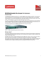
Wireless Access Point Enclosure

Part Number: PZWIFIE

Knockout to
allow the LED

Wireless Access
Point to be
visible.

lights on the

List of Components:

(4) #10-32 Hex Nuts
(4) #10 Split Lock Washers
(4) #8-32 Hex Nuts
(4) #8 Split Lock Washers
(1) Grounding Cable
(4) Pieces of Fire Resistant Foam
(1) 26" length Grommet Edging
(1) 2 Position Surface Mount Box
     (

PANDUIT

 Part No. CBXJ2WH-A)

(1) 2' long Cat5 Patch Cord
     (

PANDUIT

 Part No. UTPCH2)

(1) Cat5e Jack Module
     (

PANDUIT

 Part No. CJ5E88TWH)

(1) Foam Retention Plate
(1) Slot Cover
(1) Key

PZWIFIE

Keyed Knockout 
Slots for Wall 

Brackets for Fire
Resistant Foam

Mount Application

(2 places)

Double Knockout
for 1/2" or 3/4"
Conduit  (3 places)

Knockout Holes for
Externally Mounted
Antennas

Antenna Knockouts
for In-Ceiling Mount
Application

Slot for 802.11a
5GHz Antenna

Knockouts

 for Surface

Raceway
(2 places)

Antenna Knockouts
for External Wall
Mount Application

(door removed from view for clarity)

#10-32 threaded
Grounding Studs

(6 places)

#10-32

#10

#8-32

#8

Hardware Guide

Page 1 of 8

TABLE OF CONTENTS


Page (s)

External Wall Mount Installation ........................................................................................  2-4

Optional Flush Wall Mount Installation .....................................................................................    4

In-Ceiling Mount Installation ..............................................................................................  5-8

Summary of Contents for PZWIFIE

Page 1: ...rt No UTPCH2 1 Cat5e Jack Module PANDUIT Part No CJ5E88TWH 1 Foam Retention Plate 1 Slot Cover 1 Key PZWIFIE Keyed Knockout Slots for Wall Brackets for Fire Resistant Foam Mount Application 2 places D...

Page 2: ...nfiguration Please read these instructions in their entirety prior to installing the enclosure 2 2 x 4 Stud 1 1 Determine whether the network cable will be routed into the enclosure through conduit or...

Page 3: ...on of the three keyed mounting holes on the bracket 5 4 Pull the WAP downward until an audible snap is heard Lightly pull the WAP in the opposite direction to verify that it is properly locked into pl...

Page 4: ...t to identify the appropriate antenna configuration if the 802 11b or 802 11g radio modules on the WAP will be used 1 3 Each sidewall of the enclosure has four small knockouts that can be removed to a...

Page 5: ...ts in desired cable entry location For Conduit Remove knockout A B or C This double knockout accommodates either 1 2 or 3 4 conduit Without Conduit Remove knockout A or B Remove the 1 2 diameter openi...

Page 6: ...Observe how the hanger wire used to hold the ceiling support grid is secured to the building structure 5 3 Remove one tile adjacent to the tile the enclosure will be mounted in 5 4 Secure four pieces...

Page 7: ...of the cover 8 6 Snap the cover onto the base Note A second Cat5e Jack Module can be installed in position 2 of the surface mount box to provide access to the serial port on the WAP 6 1 Run cable from...

Page 8: ...when network cable is routed into the enclosure without the use of conduit in flush wall mount and in ceiling mount applications 9 1 Place two pieces of fire resistant foam into the foam retention bra...

Reviews: