1
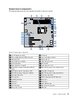
8-pin power connector
Used to connect the 8-pin power cable of the power supply.
2
CPU socket
Used to install the CPU.
3
PMBus connector
Used to connect to the PMBus connector on the power distribution board for the hot-swap power supplies.
4
24-pin main power connector
Used to connect the 24-pin power cable of the power supply.
5
Main power LED
Indicates the working status of the power supply to the system board.
Main power LED
Description
Green
The system board is powered normally.
Off
The system board is not powered normally.
6
Memory slots
Used to install memory modules. For detailed information, see “Memory module installation rules” on
page 60.
7
Front system fan 2 connector
Used to connect the cable of the front system fan 2.
8
Front system fan 2 LED
Indicates the working status of the front system fan 2.
Front system fan 2 LED
Description
Blinking amber
The fan has failed.
Off
The fan is working normally.
9
CPU fan connector
Used to connect the CPU fan on the CPU heat sink.
34
ThinkServer TS460 User Guide and Hardware Maintenance Manual
Summary of Contents for ThinkServer TS460
Page 14: ...xii ThinkServer TS460 User Guide and Hardware Maintenance Manual ...
Page 18: ...4 ThinkServer TS460 User Guide and Hardware Maintenance Manual ...
Page 52: ...38 ThinkServer TS460 User Guide and Hardware Maintenance Manual ...
Page 68: ...54 ThinkServer TS460 User Guide and Hardware Maintenance Manual ...
Page 138: ...124 ThinkServer TS460 User Guide and Hardware Maintenance Manual ...
Page 144: ...130 ThinkServer TS460 User Guide and Hardware Maintenance Manual ...
Page 148: ...134 ThinkServer TS460 User Guide and Hardware Maintenance Manual ...
Page 160: ...146 ThinkServer TS460 User Guide and Hardware Maintenance Manual ...
Page 171: ......
Page 172: ......

