Lenovo ThinkPad T470 20HD Hardware Maintenance Manual Download Page 90

If no diagnostic program is installed on the computer, the customer should download and install the program 
to diagnose the battery, before getting a non-physically damaged battery replaced. Note that the 
replacement of a physically damaged battery is not covered by the warranty.

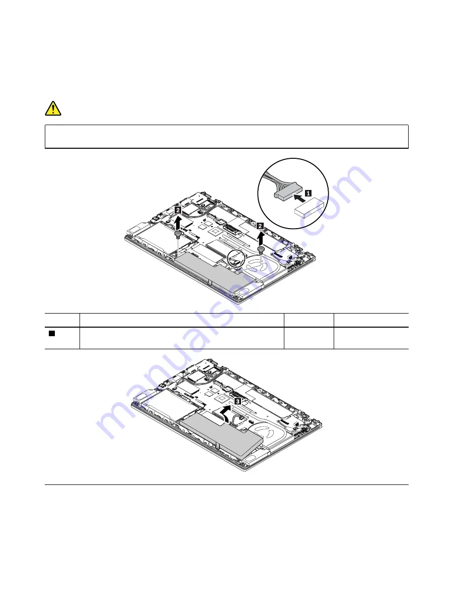
Removal steps of the built-in battery

DANGER

Use only the authorized battery specified for your computer. Any other battery could ignite or 
explode.

Step

Screw (quantity)

Color

Torque

2

M2 × 3 mm, small-head, nylon-coated (3)

Black

0.181 Nm 
(1.85 kgf-cm)

1130 Smart-card reader assembly

Note:

Before you start the servicing, disable the built-in battery. See “Disabling the built-in battery” on page 

68.

For access, remove these FRUs in order: 
•  “1010 Removable battery” on page 68

84

T470 Hardware Maintenance Manual

Summary of Contents for ThinkPad T470 20HD

Page 1: ...T470 Hardware Maintenance Manual ...

Page 2: ...er Appendix A Notices on page 105 Fourth Edition August 2017 Copyright Lenovo 2017 LIMITED AND RESTRICTED RIGHTS NOTICE If data or software is delivered pursuant to a General Services Administration GSA contract use reproduction or disclosure is subject to restrictions set forth in Contract No GS 35F 05925 ...

Page 3: ...the Windows 7 operating system 33 Recovery information for the Windows 10 operating system 34 Passwords 36 Power on password 36 Hard disk password 36 Supervisor password 36 How to remove the power on password 37 How to remove the hard disk password 37 Power management 38 Screen blank mode for the Windows 7 operating system only 38 Sleep mode 38 Hibernation mode 38 Symptom to FRU index 39 Numeric e...

Page 4: ...l fan assembly 86 1160 System board 88 1170 Power button card 90 1180 Fingerprint reader card 91 1190 NFC module 92 1200 LCD unit 93 1210 dc in cable assembly 95 1220 Keyboard bezel assembly 96 2010 LCD bezel sheet 97 2020 LCD panel 97 2030 LCD hinge assembly 98 2040 Camera microphone module 99 2050 LCD cable camera microphone module and LED cable 100 2060 Wireless LAN WAN antenna assembly WiGig a...

Page 5: ...troubleshoot problems Important This manual is intended only for trained service technicians who are familiar with ThinkPad products Use this manual along with the advanced diagnostic tests to troubleshoot problems effectively Before servicing a ThinkPad product be sure to read all the information under Chapter 1 Safety information on page 1 and Chapter 2 Important service information on page 21 C...

Page 6: ...iv T470 Hardware Maintenance Manual ...

Page 7: ...r toolcase away from walk areas so that other people will not trip over it Do not wear loose clothing that can be trapped in the moving parts of a machine Make sure that your sleeves are fastened or rolled up above your elbows If your hair is long fasten it Insert the ends of your necktie or scarf inside clothing or fasten it with a nonconductive clip about 8 centimeters 3 inches from the end Do n...

Page 8: ...safety sections of maintenance information Use extreme care when measuring high voltages Regularly inspect and maintain your electrical hand tools for safe operational condition Do not use worn or broken tools and testers Never assume that power has been disconnected from a circuit First check that it has been powered off Always look carefully for possible hazards in your work area Examples of the...

Page 9: ... frayed or pinched cables 9 Check that the power supply cover fasteners screws or rivets have not been removed or tampered with Handling devices that are sensitive to electrostatic discharge Any computer part containing transistors or integrated circuits ICs should be considered sensitive to electrostatic discharge ESD ESD damage can occur when there is a difference in charge between objects Prote...

Page 10: ...ts Electrical grounding of the computer is required for operator safety and correct system function Proper grounding of the electrical outlet can be verified by a certified electrician Safety notices multilingual translations The safety notices in this section are provided in the following languages English Arabic Brazilian Portuguese French German Hebrew Japanese Korean Spanish Traditional Chines...

Page 11: ...DANGER DANGER DANGER DANGER DANGER Chapter 1 Safety information 5 ...

Page 12: ...6 T470 Hardware Maintenance Manual ...

Page 13: ...PERIGO PERIGO Chapter 1 Safety information 7 ...

Page 14: ...PERIGO PERIGO PERIGO PERIGO PERIGO 8 T470 Hardware Maintenance Manual ...

Page 15: ...PERIGO DANGER DANGER DANGER DANGER Chapter 1 Safety information 9 ...

Page 16: ...DANGER DANGER DANGER DANGER VORSICHT 10 T470 Hardware Maintenance Manual ...

Page 17: ...VORSICHT VORSICHT VORSICHT VORSICHT Chapter 1 Safety information 11 ...

Page 18: ...VORSICHT VORSICHT VORSICHT 12 T470 Hardware Maintenance Manual ...

Page 19: ...Chapter 1 Safety information 13 ...

Page 20: ...14 T470 Hardware Maintenance Manual ...

Page 21: ...Chapter 1 Safety information 15 ...

Page 22: ...16 T470 Hardware Maintenance Manual ...

Page 23: ...Chapter 1 Safety information 17 ...

Page 24: ...18 T470 Hardware Maintenance Manual ...

Page 25: ...Chapter 1 Safety information 19 ...

Page 26: ...20 T470 Hardware Maintenance Manual ...

Page 27: ...S is loaded to the system board before completing the service action To download software fixes drivers and UEFI BIOS go to http www lenovo com ThinkPadDrivers and follow the instructions on the screen Use the following strategy to prevent unnecessary expense for replacing and servicing FRUs If you are instructed to replace a FRU but the replacement does not correct the problem reinstall the origi...

Page 28: ... where it is built and shipped directly to the customer The machine label and eSupport will load these products as the 4 character MT 4 character model and 2 character country code The model is CTO1 and the default country code is WW example 20AACTO1WW Special bid model This is a unique configuration that has been negotiated between Lenovo and the customer A unique machine type model MTM consists ...

Page 29: ...ist for a product To get the general FRU list for a product do the following 1 Go to http www lenovo com support 2 Click Parts Accessories 3 Follow the instructions on the screen to select product 4 Click Products and Parts Detail 5 On the PRODUCT AND PARTS DETAIL page click the Parts Detail tab to view the FRU list Note The FRU list is a general list of components and does not contain specific mo...

Page 30: ...24 T470 Hardware Maintenance Manual ...

Page 31: ... failures can occur for a variety of reasons that have nothing to do with a hardware defect such as cosmic radiation electrostatic discharge or software errors Consider replacing a FRU only when a problem recurs If you suspect that a FRU is defective clear the error log and run the test again If the error does not recur do not replace the FRU Be careful not to replace a nondefective FRU What to do...

Page 32: ...ers Note The diagnostic tests are intended to test only ThinkPad products The use of non ThinkPad products prototype cards or modified options can lead to false indications of errors and invalid system responses 1 Identify the failing symptoms in as much detail as possible 2 Verify the symptoms Try to re create the failure by running the diagnostic test or by repeating the operation Diagnosing pro...

Page 33: ...he troubleshooting information or the diagnostic programs might tell you that you need additional or updated device drivers or other software You can get the latest technical information and download device drivers and updates from the Lenovo Support Web site at http www lenovo com support For additional information see the Lenovo Companion help system Quick test programs Lenovo provides quick tes...

Page 34: ...an create a bootable diagnostic medium on a Universal Serial Bus USB device or CD To create a bootable diagnostic medium do the following 1 Go to http www lenovo com diags 2 Click Lenovo Bootable Diagnostics 3 Follow the instructions on the Web site to create a bootable diagnostic medium on a USB device or CD To use the diagnostic medium you have created do one of the following If you have created...

Page 35: ...y checkouts Checking the ac power adapter on page 29 Checking the removable battery and the operational charging on page 30 Checking the coin cell battery on page 31 Checking the ac power adapter You are here because the computer fails only when the ac power adapter is used If the power problem occurs only when the docking station or the port replicator is used replace the docking station or the p...

Page 36: ...ed builder The system does not support unauthorized batteries or batteries designed for other systems If an unauthorized battery or a battery designed for another systems is installed the system will not charge Attention Lenovo has no responsibility for the performance or safety of unauthorized batteries and provides no warranties for failures or damage arising out of their use Move your pointer t...

Page 37: ...e the battery and let it return to room temperature 3 Reinstall the battery If the battery is still not charging replace the battery 4 Check the battery status icon again If the same error still exists replace the system board Checking the coin cell battery To check the coin cell battery do the following 1 Disable the built in battery See Disabling the built in battery on page 68 2 Remove the coin...

Page 38: ...32 T470 Hardware Maintenance Manual ...

Page 39: ...nding on the model the number of recovery discs included in the Recovery Disc Set differs The Recovery Disc Set might consist of the user instructions and the following set of DVDs to restore the computer to the original factory configuration Operating System Recovery Disc one disc This disc restores the Microsoft Windows operating system Use this disc to start the recovery process Applications an...

Page 40: ...s apparent on the screen for several minutes at a time This is normal 10 When the recovery process is complete the Set Up Windows screen is displayed Follow the instructions on the screen to complete the Windows setup 11 After you have completed the Windows setup you might want to restore the original startup sequence Start the ThinkPad Setup program and then press F9 to restore the default settin...

Page 41: ...er is connected to ac power during the recovery process Creating and using a recovery USB drive You can create a recovery USB drive as a backup for the Windows recovery programs With the recovery USB drive you can troubleshoot and fix the problems even if the preinstalled Windows recovery programs are damaged Creating a recovery USB drive The USB drive that you use to create the recovery USB drive...

Page 42: ...get access to the hard disk even if the user has changed the user hard disk password Note There are two modes for the hard disk password User only and Master User The Master User mode requires two hard disk passwords the system administrator enters both in the same operation The system administrator then provides the user hard disk password to the system user Attention If the user hard disk passwo...

Page 43: ...emovable battery on page 68 8 Turn on the computer and wait until the power on self test POST ends After the POST ends the password prompt does not appear The power on password has been removed If a supervisor password has been set and is known to the service technician do the following to remove the power on password 1 Turn on the computer 2 When the logo screen comes up immediately press F1 3 Ty...

Page 44: ... mode do the following 1 Right click the battery status indicator on the taskbar 2 Select Power off display To end screen blank mode and resume normal operation press any key Sleep mode When the computer enters sleep mode the following events occur in addition to what occurs in screen blank mode The LCD is powered off The hard disk drive or solid state drive is powered off The microprocessor stops...

Page 45: ...ation Numeric error codes on page 40 Error messages on page 41 Beep errors on page 41 No beep symptoms on page 43 LCD related symptoms on page 43 Intermittent problems on page 44 Undetermined problems on page 44 The symptom to FRU index in this section lists symptoms and errors and their possible causes The most likely cause is listed first in boldface type Note Do the FRU replacement or other act...

Page 46: ...ecurity Security password retry count exceeded 1 Run the ThinkPad Setup program The retry count will be reset Then save the current settings by pressing F10 2 Replace the system board 0270 Real Time Clock Error System Real Time Clock is not functional Have the computer serviced 0271 Check Date and Time settings Neither the date nor the time is set in the computer Set the date and time using ThinkP...

Page 47: ...e 3 Replace the system board Thermal sensing error Replace the system board The battery installed is not supported by this system and will not charge Please replace the battery with the correct Lenovo battery for this system Press the ESC key to continue Replace the battery pack This system does not support batteries that are not genuine Lenovo made or authorized The system will continue to boot b...

Page 48: ...puter by inserting a straightened paper clip into the emergency reset hole Wait for one minute Then reconnect all power resources 2 Replace the system board service provider only 0002 Internal bus error Replace the system board service provider only 0281 General embedded controller error Replace the system board service provider only 0282 Memory module error 1 Reinstall or replace the memory modul...

Page 49: ...portant The TFT LCD for the notebook computer contains many thin film transistors TFTs The presence of a small number of dots that are missing discolored or always lighted is characteristic of TFT LCD technology but excessive pixel problems can cause viewing concerns If the LCD you are servicing has two or less visible defective pixels it should not be considered faulty However if the LCD has thre...

Page 50: ... diagnostic tests did not identify the adapter or device that has failed if wrong devices are installed or if the system simply is not operating follow these procedures to isolate the failing FRU do not isolate FRUs that have no defects Verify that all attached devices are supported by the computer Verify that the power supply being used at the time of the failure is operating correctly See Power ...

Page 51: ... slowly The computer is in sleep mode On The computer is on in normal mode Off The computer is off or in hibernation mode On The microphones are muted 3 Caps Lock indicator On You can type uppercase letters by directly pressing the letter keys 4 Fn Lock indicator Off The Fn Lock function is disabled You can use the default function You can change the default function in the Keyboard Properties win...

Page 52: ...46 T470 Hardware Maintenance Manual ...

Page 53: ...n you turn on your computer again To turn on the sound press F2 or F3 Decrease the speaker volume Increase the speaker volume Mute or unmute the microphones When the microphones are muted the indicator on the key is on Darken the computer display Brighten the computer display Manage external displays F8 Enable or disable the built in wireless features F9 For Windows 7 Open Control Panel For Window...

Page 54: ...g page you can also define different functions for the key combinations with F12 such as Shift F12 Alt F12 or Ctrl F12 Fn PrtSc Open the Snipping Tool program Fn Esc Switch the key function between the standard F1 F12 function and the special function printed as an icon on each key When the Fn Lock indicator is off you can use the default function You can change the default function in the Keyboar...

Page 55: ...odels 2 Microphones 3 Infrared camera available on some models 4 Power button 5 Fingerprint reader available on some models 6 Security lock slot 7 Media card slot 8 Ethernet connector 9 USB 3 0 connector 10 High Definition Multimedia Interface HDMITM 11 USB 3 0 connector 12 Audio connector 13 TrackPoint buttons 14 Trackpad 15 Near field communication NFC label available on some models 16 TrackPoin...

Page 56: ...ers 7 Smart card slot available on some models 8 Speakers 9 Keyboard drainage holes 10 Emergency reset hole 11 Micro SIM card slot available on some models Locating FRUs and CRUs This topic introduces the following service parts Major FRUs and CRUs on page 52 LCD FRUs on page 54 Connector and cable guide on page 55 50 T470 Hardware Maintenance Manual ...

Page 57: ... instructions to find the manual for your product You might be required to return the defective part that is replaced by the CRU When return is required 1 return instructions a prepaid shipping label and a container will be included with the replacement CRU and 2 you might be charged for the replacement CRU if Lenovo does not receive the defective CRU within thirty 30 days of your receipt of the r...

Page 58: ...s No FRU descriptions Self service CRU Optional service CRU 1 LCD unit No No 2 Trackpad No No 3 Keyboard bezel assembly No No 4 Power button board No No 5 Fingerprint reader bracket on some models No No 52 T470 Hardware Maintenance Manual ...

Page 59: ...5 bracket No No 14 Removable battery Yes No 15 SIM card on some models Yes No 16 Base cover assembly Yes No 17 Built in battery No No 18 Speaker assembly No No 19 Thermal fan assembly No No 20 System board No No 21 Coin cell battery Yes No 22 Memory modules No Yes 23 Smart card reader and cable on some models No No 24 NFC antenna No No 25 NFC module and cable on some models No No 26 IO bracket No ...

Page 60: ...o 3 LCD cable No No 4 Camera microphone module and LED cable No No 5 Conventional camera microphone module No No 6 Infrared camera microphone module on some models No No 7 Wireless LAN antenna Wireless WAN antenna on some models and WiGig antenna on some models No No 8 LCD hinge assembly No No 54 T470 Hardware Maintenance Manual ...

Page 61: ... L3 black 20 No No System miscellaneous parts kit IO bracket RJ45 bracket Speaker rubbers Sheet support rubber Microphone rubbers Fingerprint reader bracket assembly NFC ferrite sheet NFC sponge Smartcard safety mylar No No GEO label assembly No No Connector and cable guide This section provides information for Lenovo authorized service technicians to help identify connectors and cables for replac...

Page 62: ...nnector external No Connect the removable battery to this connector 4 Micro SIM card slot external No Insert the micro SIM card into this slot 5 Docking station connector external No Connect the dock to this connector 6 Coin cell battery connector internal Coin cell battery cable The coin cell battery comes with cable Connect the cable to this connector 7 LCD connector internal LCD cable Connect o...

Page 63: ...eader connector internal Fingerprint reader cable Connect one end to the fingerprint reader and the other end to this connector 19 Trackpad connector internal Trackpad cable Connect the Trackpad cable to this connector 20 Wireless WAN card slot internal No Insert the wireless WAN card into this slot 21 Speaker connector internal Speaker assembly cable The speaker assembly comes with cable Connect ...

Page 64: ...gray antenna to the A cover and the other end to this connector 2 Wireless LAN antenna connector internal Wireless LAN antenna kit Connect one end of the wireless LAN black antenna to the A cover and the other end to this connector Wireless WAN card connectors and cables Table 14 Wireless WAN card It em Connector location Internal cable required Cable connection 1 Wireless WAN antenna connector in...

Page 65: ...nd the other end to this connector 3 Wireless LAN antenna connector internal Wireless LAN antenna kit Connect one end of the wireless LAN black antenna to the A cover and the other end to this connector Fingerprint reader connector and cable Table 16 Fingerprint reader connector and cable It em Connector location Internal cable required Cable connection 1 Fingerprint reader card connector internal...

Page 66: ...end to this connector 2 NFC antenna connector internal NFC antenna cable Connect the NFC antenna cable to this connector Power button card and cable Table 19 Power button card It em Connector location Internal cable required Cable connection 1 Power button card connector internal Power button card cable Connect one end to the power button card connector on the system board and the other end to thi...

Page 67: ...ackpad connector internal Trackpad cable Connect one end to the trackpad connector on the system board and the other end to this connector Looking up FRU information For detailed FRU information including part numbers descriptions and substitution part numbers go to http www lenovo com serviceparts lookup Chapter 7 Locations 61 ...

Page 68: ...62 T470 Hardware Maintenance Manual ...

Page 69: ...r your product You might be required to return the defective part that is replaced by the CRU When return is required 1 return instructions a prepaid shipping label and a container will be included with the replacement CRU and 2 you might be charged for the replacement CRU if Lenovo does not receive the defective CRU within thirty 30 days of your receipt of the replacement CRU See your Lenovo Limi...

Page 70: ...l number of the system unit on the bottom of the computer try the following method to get the number Note Before you perform the operation ensure that the UEFI Legacy setting within the Startup menu in the ThinkPad Setup program is set to UEFI Only 1 Connect a USB memory key to the computer 2 Go to http www lenovo com maintenanceutilities and follow the instructions on the screen to create a Maint...

Page 71: ...ype 2 under Enter the action desired then press Enter The Auto UUID generation utility interface is displayed 6 Type y under Change UUID OK Y N then press Enter A new UUID is created and written If a valid UUID already exists it is not overwritten Reading or writing the ECA information Information on Engineering Change Announcements ECA is stored in the EEPROM of the system board The electronic st...

Page 72: ...ct 1 Write ECA rework number from EEPROM and follow the instruction To write box build date select 4 Write box build date from EEPROM and follow the instruction on the screen If the system board is being replaced try to read the ECA information from the old system board and transfer the information to the new system If the system board is inoperable this will not be possible 66 T470 Hardware Maint...

Page 73: ...re to observe the following general guidelines 1 Do not try to service any computer unless you have been trained and certified An untrained person runs the risk of damaging parts 2 Before replacing any FRU review Chapter 8 FRU replacement notices on page 63 3 Begin by removing any FRUs that have to be removed before replacing the failing FRU Any such FRUs are listed at the beginning of each FRU re...

Page 74: ...abled and the computer turns off automatically Wait three to five minutes to let the computer cool 1010 Removable battery Important notices for replacing a removable battery Attention Lenovo has no responsibility for the performance or safety of unauthorized batteries and provides no warranties for failures or damage arising out of their use Lenovo provides a diagnostic program to do an automatic ...

Page 75: ...abling the built in battery on page 68 Removal steps of the micro SIM card 1030 Base cover assembly Note Before you start the servicing disable the built in battery See Disabling the built in battery on page 68 For access remove these FRUs 1010 Removable battery on page 68 Chapter 9 Removing or replacing a FRU 69 ...

Page 76: ... assembly 1 Loosen the screws 1 2 Remove the base cover assembly in the numeric order as shown Applying labels to the base cover assembly The following illustration shows the location of each label 70 T470 Hardware Maintenance Manual ...

Page 77: ...abel 14 Swiss SIM ICCID label 15 Malaysian SLP label 16 BIS label 17 FCC label 18 KCC safety label 19 Taiwan WWAN label 20 Argentina CNC label 21 Indonesia POSTEL label 1040 Memory module Note Before you start the servicing disable the built in battery See Disabling the built in battery on page 68 For access remove these FRUs in order 1010 Removable battery on page 68 1030 Base cover assembly on p...

Page 78: ...ble the built in battery See Disabling the built in battery on page 68 For access remove these FRUs in order 1010 Removable battery on page 68 1030 Base cover assembly on page 69 Attention Do not drop the drive or apply any physical shock to it The drive is sensitive to physical shock Improper handling can cause damage and permanent loss of data Before removing the drive have the user make a backu...

Page 79: ...Removal steps of the 2 5 inch storage drive Chapter 9 Removing or replacing a FRU 73 ...

Page 80: ...Removal steps of the M 2 solid state drive 74 T470 Hardware Maintenance Manual ...

Page 81: ...Step Screw quantity Color Torque 6 M2 3 mm flat head nylon coated 2 Black 0 181 Nm 1 85 kgf cm 8 M2 3 mm flat head nylon coated 1 Black 0 181 Nm 1 85 kgf cm Chapter 9 Removing or replacing a FRU 75 ...

Page 82: ...id state drive is firmly attached and the tape does not cover the speaker 1060 Wireless WAN card Note Before you start the servicing disable the built in battery See Disabling the built in battery on page 68 For access remove these FRUs in order 1010 Removable battery on page 68 1030 Base cover assembly on page 69 76 T470 Hardware Maintenance Manual ...

Page 83: ...nto the connector labeled AUX on the card If a green cable comes with your computer plug the cable into the connector with the silkscreen GPS 1070 Wireless LAN module or WiGig module Note Before you start the servicing disable the built in battery See Disabling the built in battery on page 68 For access remove these FRUs in order 1010 Removable battery on page 68 1030 Base cover assembly on page 6...

Page 84: ...mm flat head nylon coated 1 Black 0 181 Nm 1 85 kgf cm When installing Plug the gray cable into the connector labeled MAIN or 2 on the card and plug the black cable into the connector labeled AUX or 1 on the card Removal steps of the WiGig module 78 T470 Hardware Maintenance Manual ...

Page 85: ...sable the built in battery See Disabling the built in battery on page 68 For access remove these FRUs in order 1010 Removable battery on page 68 1030 Base cover assembly on page 69 Removal steps of the M 2 solid state drive in the Wireless WAN card slot Step Screw quantity Color Torque 2 M2 3 mm flat head nylon coated 1 Black 0 181 Nm 1 85 kgf cm When installing Ensure that the M 2 solid state dri...

Page 86: ...rn the computer over and open the display Push hard in the direction as shown to release the latches from the keyboard bezel 2 2 Pivot the keyboard slightly upward as shown by the arrow 4 until you can see the connectors on the bottom side of the keyboard Then turn over the keyboard as shown by the arrow 5 80 T470 Hardware Maintenance Manual ...

Page 87: ... 6 7 8 9 1100 Coin cell battery Note Before you start the servicing disable the built in battery See Disabling the built in battery on page 68 For access remove these FRUs in order 1010 Removable battery on page 68 1030 Base cover assembly on page 69 Chapter 9 Removing or replacing a FRU 81 ...

Page 88: ...at the connector of the coin cell battery is attached firmly 1110 Speaker assembly Note Before you start the servicing disable the built in battery See Disabling the built in battery on page 68 For access remove these FRUs in order 1010 Removable battery on page 68 1030 Base cover assembly on page 69 Removal steps of the speaker assembly 82 T470 Hardware Maintenance Manual ...

Page 89: ...68 For access remove these FRUs in order 1010 Removable battery on page 68 1030 Base cover assembly on page 69 Important notices for replacing a built in battery Attention Lenovo has no responsibility for the performance or safety of unauthorized batteries and provides no warranties for failures or damage arising out of their use Lenovo provides a diagnostic program to do an automatic battery diag...

Page 90: ... steps of the built in battery DANGER Use only the authorized battery specified for your computer Any other battery could ignite or explode Step Screw quantity Color Torque 2 M2 3 mm small head nylon coated 3 Black 0 181 Nm 1 85 kgf cm 1130 Smart card reader assembly Note Before you start the servicing disable the built in battery See Disabling the built in battery on page 68 For access remove the...

Page 91: ...on coated 2 Black 0 181 Nm 1 85 kgf cm When installing Ensure that the connector of the smart card reader is attached firmly 1140 I O bracket and RJ45 bracket Note Before you start the servicing disable the built in battery See Disabling the built in battery on page 68 For access remove these FRUs 1010 Removable battery on page 68 1030 Base cover assembly on page 69 Chapter 9 Removing or replacing...

Page 92: ...oated 3 Sliver 0 181 Nm 1 85 kgf cm 1150 Thermal fan assembly Note Before you start the servicing disable the built in battery See Disabling the built in battery on page 68 For access remove these FRUs in order 1010 Removable battery on page 68 1030 Base cover assembly on page 69 Removal steps of the thermal fan assembly Notes Loosen the screws in ascending alphabetical order as illustrated 86 T47...

Page 93: ...rmal grease at an amount of 0 2 grams on the parts marked a and b as shown in the following illustration Either too much or too less application of grease can cause a thermal problem due to imperfect contact with a component For the new thermal fan assembly you must peel off the thin film from the rubbers For integrated graphics models For discrete graphics models Chapter 9 Removing or replacing a...

Page 94: ...Disabling the built in battery on page 68 For access remove these FRUs in order 1010 Removable battery on page 68 1020 Micro SIM card on page 69 1030 Base cover assembly on page 69 1040 Memory module on page 71 1050 Internal storage drive on page 72 1060 Wireless WAN card on page 76 or 1080 M 2 solid state drive in the Wireless WAN card slot on page 79 1070 Wireless LAN module or WiGig module on p...

Page 95: ...Note The graphics chip a is only for discrete graphics models c d Removal steps of the system board Chapter 9 Removing or replacing a FRU 89 ...

Page 96: ...on page 69 1030 Base cover assembly on page 69 1040 Memory module on page 71 1050 Internal storage drive on page 72 1060 Wireless WAN card on page 76 or 1080 M 2 solid state drive in the Wireless WAN card slot on page 79 1070 Wireless LAN module or WiGig module on page 77 1090 Keyboard on page 79 1100 Coin cell battery on page 81 1110 Speaker assembly on page 82 1120 Built in battery on page 83 11...

Page 97: ...on page 68 1020 Micro SIM card on page 69 1030 Base cover assembly on page 69 1040 Memory module on page 71 1050 Internal storage drive on page 72 1060 Wireless WAN card on page 76 or 1080 M 2 solid state drive in the Wireless WAN card slot on page 79 1070 Wireless LAN module or WiGig module on page 77 1090 Keyboard on page 79 1100 Coin cell battery on page 81 1110 Speaker assembly on page 82 1120...

Page 98: ...le battery on page 68 1020 Micro SIM card on page 69 1030 Base cover assembly on page 69 1040 Memory module on page 71 1050 Internal storage drive on page 72 1060 Wireless WAN card on page 76 or 1080 M 2 solid state drive in the Wireless WAN card slot on page 79 1070 Wireless LAN module or WiGig module on page 77 1090 Keyboard on page 79 1100 Coin cell battery on page 81 1110 Speaker assembly on p...

Page 99: ...ps of the NFC module 1200 LCD unit Note Before you start the servicing disable the built in battery See Disabling the built in battery on page 68 For access remove these FRUs in order 1010 Removable battery on page 68 1030 Base cover assembly on page 69 Removal steps of the LCD unit Chapter 9 Removing or replacing a FRU 93 ...

Page 100: ...Step Screw quantity Color Torque 9 M2 5 4 mm flat head nylon coated 5 Black 0 293 Nm 3 0 kgf cm 94 T470 Hardware Maintenance Manual ...

Page 101: ... that the connectors are attached firmly 1210 dc in cable assembly Note Before you start the servicing disable the built in battery See Disabling the built in battery on page 68 For access remove these FRUs in order 1010 Removable battery on page 68 1030 Base cover assembly on page 69 1200 LCD unit on page 93 Removal steps of the dc in cable assembly Chapter 9 Removing or replacing a FRU 95 ...

Page 102: ...60 Wireless WAN card on page 76 or 1080 M 2 solid state drive in the Wireless WAN card slot on page 79 1070 Wireless LAN module or WiGig module on page 77 1090 Keyboard on page 79 1100 Coin cell battery on page 81 1110 Speaker assembly on page 82 1120 Built in battery on page 83 1130 Smart card reader assembly on page 84 1140 I O bracket and RJ45 bracket on page 85 1150 Thermal fan assembly on pag...

Page 103: ...9 Removal steps of the LCD bezel sheet When installing Install a new LCD bezel sheet whenever the old one is removed Ensure that all the latches are attached firmly 2020 LCD panel Note Before you start the servicing disable the built in battery See Disabling the built in battery on page 68 For access remove these FRUs in order 1010 Removable battery on page 68 1030 Base cover assembly on page 69 C...

Page 104: ...at the connector of the LCD cable is attached firmly 2030 LCD hinge assembly Note Before you start the servicing disable the built in battery See Disabling the built in battery on page 68 For access remove these FRUs in order 1010 Removable battery on page 68 1030 Base cover assembly on page 69 1200 LCD unit on page 93 98 T470 Hardware Maintenance Manual ...

Page 105: ...Nm 3 0 kgf cm 2040 Camera microphone module Note Before you start the servicing disable the built in battery See Disabling the built in battery on page 68 For access remove these FRUs in order 1010 Removable battery on page 68 1030 Base cover assembly on page 69 1200 LCD unit on page 93 2010 LCD bezel sheet on page 97 2020 LCD panel on page 97 Chapter 9 Removing or replacing a FRU 99 ...

Page 106: ...d LED cable Note Before you start the servicing disable the built in battery See Disabling the built in battery on page 68 For access remove these FRUs in order 1010 Removable battery on page 68 1030 Base cover assembly on page 69 1200 LCD unit on page 93 2010 LCD bezel sheet on page 97 2020 LCD panel on page 97 100 T470 Hardware Maintenance Manual ...

Page 107: ...060 Wireless LAN WAN antenna assembly WiGig antenna assembly and LCD rear cover assembly Note Before you start the servicing disable the built in battery See Disabling the built in battery on page 68 For access remove these FRUs in order 1010 Removable battery on page 68 1030 Base cover assembly on page 69 1200 LCD unit on page 93 2010 LCD bezel sheet on page 97 2020 LCD panel on page 97 2030 LCD ...

Page 108: ...cover assembly When installing Route the cables as shown in the following illustration Attention As you route the cables ensure that they are not subject to any tension Tension could cause the cables to be damaged by the cable guides or a wire to be broken 102 T470 Hardware Maintenance Manual ...

Page 109: ...y antenna black b Wireless WAN auxiliary antenna blue available on some models c WiGig module available on some models d Wireless WAN main antenna orange available on some models e Wireless LAN main antenna grey Chapter 9 Removing or replacing a FRU 103 ...

Page 110: ...104 T470 Hardware Maintenance Manual ...

Page 111: ...e publication Lenovo may make improvements and or changes in the product s and or the program s described in this publication at any time without notice The products described in this document are not intended for use in implantation or other life support applications where malfunction may result in injury or death to persons The information contained in this document does not affect or change Len...

Page 112: ...go TrackPoint Thunderbolt is a trademark of Intel Corporation or its subsidiaries in the U S and or other countries Microsoft Windows Windows Server and Cortana are trademarks of the Microsoft group of companies The terms HDMI and HDMI High Definition Multimedia Interface are trademarks or registered trademarks of HDMI Licensing LLC in the United States and other countries WiGig is a registered tr...

Page 113: ... Change Announcements EEPROM Electrically Erasable Programmable Read Only Memory EFI Extensible Firmware Interface EPO emergency power off ESD electrostatic discharge EU European Union FCC Federal Communications Commission FRU Field Replaceable Unit GAV General Announce Variant GPU graphics processing unit HDD hard disk drive HDMI high definition multimedia interface ICs integrated circuits ICCID ...

Page 114: ...red jack SATA Serial Advanced Technology Attachment SIM subscriber identity module SVP supervisor password TFTs thin film transistors UEFI Unified Extensible Firmware Interface USB Universal Serial Bus UUID universally unique identifier VGA video graphics array VRAM video random access memory WAN wide area network 108 T470 Hardware Maintenance Manual ...

Page 115: ......

Page 116: ...Part Number SP40M11890_03 Printed in 1P P N SP40M11890_03 1PSP40M11890_03 ...

Reviews: