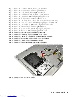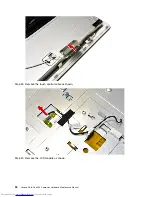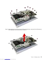
Step 17. Remove the LVDS cable from the connector on the LCD, then lift up the LCD panel from the
front bezel.
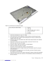
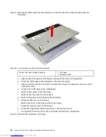
Step 18. To install the new the LCD panel module:
The new LED panel module including:
1. LED panel
2. Converter cable
a.
Align the new LCD panel with front bezel, then place the new LCD into position.
b.
Attach the LVDS cable to the connector on the new LCD panel.
c.
Align the chassis with the front bezel, then place the chassis into position and secure it with
seventeen screws.
d.
Connect the LVDS cable to the motherboard.
e.
Reattach the camera to the front bezel.
f.
Reattach the converter to the front bezel.
g.
Reattach the power switch board to the front bezel.
h.
Attach the EMI cover to the chassis.
i.
Reathe rear cover to the chassis with the six screws.
j.
Attach the hard disk drive to the chassis.
k.
Attach the hinge to the chassis and secure it with the four screws.
l.
Line up the foot cover with rear cover, and slide the foot cover into position.
Step 19. Reattach the stand base with hinge.
54
Lenovo All-In-One 300 Computer Hardware Maintenance Manual
Summary of Contents for Thinkpad 300
Page 2: ......
Page 6: ...iv Lenovo All In One 300 Computer Hardware Maintenance Manual ...
Page 8: ...2 Lenovo All In One 300 Computer Hardware Maintenance Manual ...
Page 16: ...10 Lenovo All In One 300 Computer Hardware Maintenance Manual ...
Page 18: ...12 Lenovo All In One 300 Computer Hardware Maintenance Manual ...
Page 24: ...18 Lenovo All In One 300 Computer Hardware Maintenance Manual ...
Page 32: ...26 Lenovo All In One 300 Computer Hardware Maintenance Manual ...

