


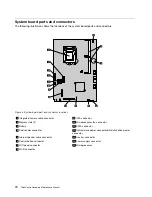


System board parts and connectors
The following illustration shows the locations of the system board parts and connectors.
Figure 4. System board part and connector locations
1
Integrated camera cable connector
9
SATA connector
2
Memory slots (2)
10
Microprocessor fan connector
3
Battery
11
SATA connector
4
Card reader connector
12
Optical drive power connector/Hard disk drive power
connector
5
Internal speaker cable connector
13
Inverter connector
6
Control button connector
14
Power supply connector
7
LCD panel connector
15
Microprocessor
8
WI-FI connector
70
ThinkCentre Hardware Maintenance Manual
Summary of Contents for ThinkCentre M72z
Page 2: ......
Page 8: ...2 ThinkCentre Hardware Maintenance Manual ...
Page 15: ...Chapter 2 Safety information 9 ...
Page 19: ...Chapter 2 Safety information 13 ...
Page 20: ...1 2 14 ThinkCentre Hardware Maintenance Manual ...
Page 21: ...Chapter 2 Safety information 15 ...
Page 27: ...Chapter 2 Safety information 21 ...
Page 31: ...Chapter 2 Safety information 25 ...
Page 38: ...32 ThinkCentre Hardware Maintenance Manual ...
Page 68: ...62 ThinkCentre Hardware Maintenance Manual ...
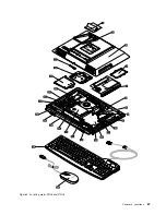
Page 73: ...Figure 3 Locating major FRUs and CRUs Chapter 8 Locations 67 ...
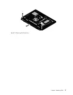
Page 83: ...Figure 12 Removing the frame stand Chapter 9 Replacing FRUs 77 ...
Page 120: ...114 ThinkCentre Hardware Maintenance Manual ...
Page 125: ......
Page 126: ......