


5. The fan assembly is mounted with four rubber mounts that protrude through the plastic mounting bracket
and the fan housing. Remove the fan assembly by pulling the rubber mounts back through the holes in
the fan housing.
6. Pull the rubber mounts loose from the mounting bracket. New rubber mounts might come with the
new fan.
7. Install the rubber mounts back into the mounting bracket.
8. Install the new fan assembly by aligning the rubber mounts in the mounting bracket with the holes in the
fan housing and pulling the rubber mounts through the holes with your fingers.
9. Reinstall the fan mounting bracket into the chassis.
10. Reconnect the fan cable, power switch or LED cable, and temperature sensor cable to the system board.
See “System board connectors” on page 121.
11. Go to “Completing the FRU replacement” on page 141.
Completing the FRU replacement
After replacing the parts, you need to close the cover and reconnect cables, including telephone lines and
power cords. Also, depending on the part that was replaced, you might need to confirm the updated
information in the Setup Utility program. Refer to Chapter 6 “Diagnostics, Test and Recovery Information”
on page 41.
1. Ensure that all components have been reassembled correctly and that no tools or loose screws are left
inside your computer. See “Computer components” on page 120 for the location of various components.
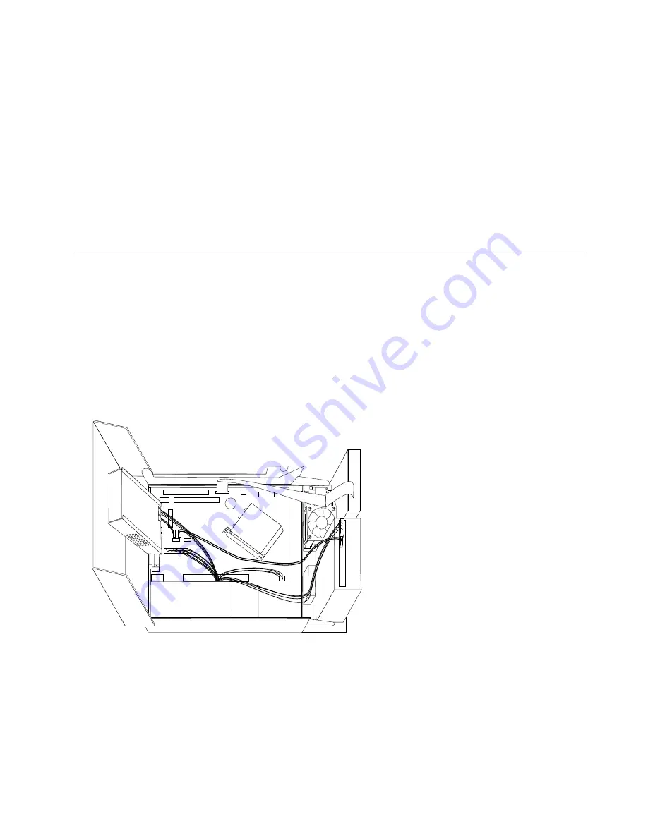
2. Make sure that the cables are routed correctly before lowering the drive-bay assembly.
Important:
Correctly route all power supply cables to avoid interference with the drive bay assembly.
Keep cables clear of the hinges and sides of the computer chassis.
3. Lower the drive-bay assembly and position the drive locks to the locked position. Otherwise, you cannot
close the computer cover.
4. Close the computer cover.
5. If a cover lock is installed, lock the cover.
6. Reconnect the external cables and power cords to the computer. See “Rear connectors” on page 119.
7. If you are replacing the system board or microprocessor, you must update (flash) the BIOS. See
“Updating (flashing) BIOS from a CD-ROM or diskette” on page 775.
8. To update your configuration, see Chapter 6 “Diagnostics, Test and Recovery Information” on page 41.
Chapter 10
.
Replacing FRUs (Types 7066, 7098, 9352, 9359, 9482, 9487, 9622, 9704, 9785, 9794, 9807, 9859, 9952)
141
Summary of Contents for ThinkCentre A57
Page 2: ......
Page 8: ...viii ThinkCentre Hardware Maintenance Manual ...
Page 17: ...Chapter 2 Safety information 9 ...
Page 21: ...Chapter 2 Safety information 13 ...
Page 22: ...1 2 14 ThinkCentre Hardware Maintenance Manual ...
Page 23: ...Chapter 2 Safety information 15 ...
Page 29: ...Chapter 2 Safety information 21 ...
Page 33: ...Chapter 2 Safety information 25 ...
Page 40: ...32 ThinkCentre Hardware Maintenance Manual ...
Page 48: ...40 ThinkCentre Hardware Maintenance Manual ...
Page 52: ...44 ThinkCentre Hardware Maintenance Manual ...
Page 76: ...68 ThinkCentre Hardware Maintenance Manual ...
Page 98: ...90 ThinkCentre Hardware Maintenance Manual ...
Page 126: ...118 ThinkCentre Hardware Maintenance Manual ...
Page 150: ...142 ThinkCentre Hardware Maintenance Manual ...
Page 787: ......
Page 788: ...Part Number 45C6545 Printed in USA 1P P N 45C6545 45C6545 ...


