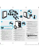
4. Disconnect the signal and power cables from the hard disk drive.
5. Press the release tab
1
down, slide the hard drive cage
2
back, and pivot the hard disk drive outward
as shown.
6. Carefully take note of the location of all cable connections on the system board and disconnect all cables.
See the system board illustration for your machine type at “System board connectors” on page 92.
7. Remove the screws that secure the system board to the chassis.
8. Lift the system board out of the chassis.
9. Remove the memory modules from the failing system board and install them in the same location on
the new system board.
10. Disconnect the heat sink and fan assembly cable from the system board. See the system board
illustration for your machine type at “System board connectors” on page 92.
11. Remove the four screws
1
securing the heat sink and fan assembly to the system board.
Chapter 9
.
Replacing FRUs (Types 7064, 7094, 9349, 9356, 9357, 9439, 9488, 9702, 9708, 9709, 9789, 9851, 9948)
97
Summary of Contents for ThinkCentre A57
Page 2: ......
Page 8: ...viii ThinkCentre Hardware Maintenance Manual ...
Page 17: ...Chapter 2 Safety information 9 ...
Page 21: ...Chapter 2 Safety information 13 ...
Page 22: ...1 2 14 ThinkCentre Hardware Maintenance Manual ...
Page 23: ...Chapter 2 Safety information 15 ...
Page 29: ...Chapter 2 Safety information 21 ...
Page 33: ...Chapter 2 Safety information 25 ...
Page 40: ...32 ThinkCentre Hardware Maintenance Manual ...
Page 48: ...40 ThinkCentre Hardware Maintenance Manual ...
Page 52: ...44 ThinkCentre Hardware Maintenance Manual ...
Page 76: ...68 ThinkCentre Hardware Maintenance Manual ...
Page 98: ...90 ThinkCentre Hardware Maintenance Manual ...
Page 126: ...118 ThinkCentre Hardware Maintenance Manual ...
Page 150: ...142 ThinkCentre Hardware Maintenance Manual ...
Page 787: ......
Page 788: ...Part Number 45C6545 Printed in USA 1P P N 45C6545 45C6545 ...


