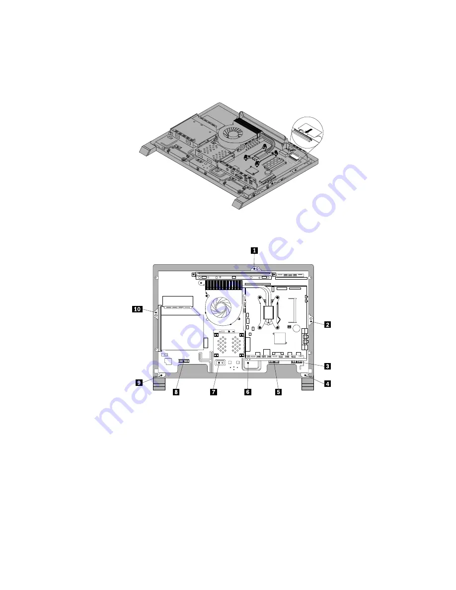
9. Disconnect the LCD panel cable from the system board. See “Locating parts on the system board”
on page 66.
Figure 34. Disconnect the LCD panel cable from the system board
10. Remove all the 10 screws that secure the computer main bracket to the front bezel.
Figure 35. Removing the 10 screws that secure the computer main bracket to the front bezel
11. Note the locations of all cable connections that prevent you from lifting the computer main bracket, and
disconnect all cables. See “Locating parts on the system board” on page 66.
12. Remove the integrated camera. See “Replacing the integrated camera” on page 88
13. Lift the computer main bracket off the front bezel.
92
Lenovo S710 All-In-OneHardware Maintenance Manual
Summary of Contents for S710
Page 1: ...Lenovo S710 All In One Hardware Maintenance Manual Machine Types 10152 F0AG ...
Page 2: ......
Page 3: ...Lenovo S710 All In One Hardware Maintenance Manual Machine Types 10152 F0AG ...
Page 8: ...2 Lenovo S710 All In OneHardware Maintenance Manual ...
Page 15: ...Chapter 2 Safety information 9 ...
Page 19: ...Chapter 2 Safety information 13 ...
Page 20: ...1 2 14 Lenovo S710 All In OneHardware Maintenance Manual ...
Page 21: ...1 2 Chapter 2 Safety information 15 ...
Page 26: ...1 2 20 Lenovo S710 All In OneHardware Maintenance Manual ...
Page 27: ...1 2 Chapter 2 Safety information 21 ...
Page 30: ...24 Lenovo S710 All In OneHardware Maintenance Manual ...
Page 34: ...28 Lenovo S710 All In OneHardware Maintenance Manual ...
Page 66: ...60 Lenovo S710 All In OneHardware Maintenance Manual ...
Page 70: ...Figure 3 Locating major FRUs and CRUs 64 Lenovo S710 All In OneHardware Maintenance Manual ...
Page 104: ...98 Lenovo S710 All In OneHardware Maintenance Manual ...
Page 117: ......
Page 118: ......


