background image

53

Lenovo ideapad Y910-17ISK

1120 Upper case

For access, remove these FRUs in order: 

‡

“1010 Base cover” on page 33

‡

“1020 Battery pack” on page 36

‡

“1030 Solid state disk and hard disk drive” on page 37

‡

“1040 PCI Express Mini Card for wireless LAN” on page 41

‡

“1060 Subwoofer” on page 44

‡

“1070 IO board” on page 45

‡

“1080 Fan assembly and Heat Sink assembly” on page 46

‡

“1090 System board” on page 48

‡

“1100 Speakers” on page 51

‡

“1110 DC-in cable” on page 52

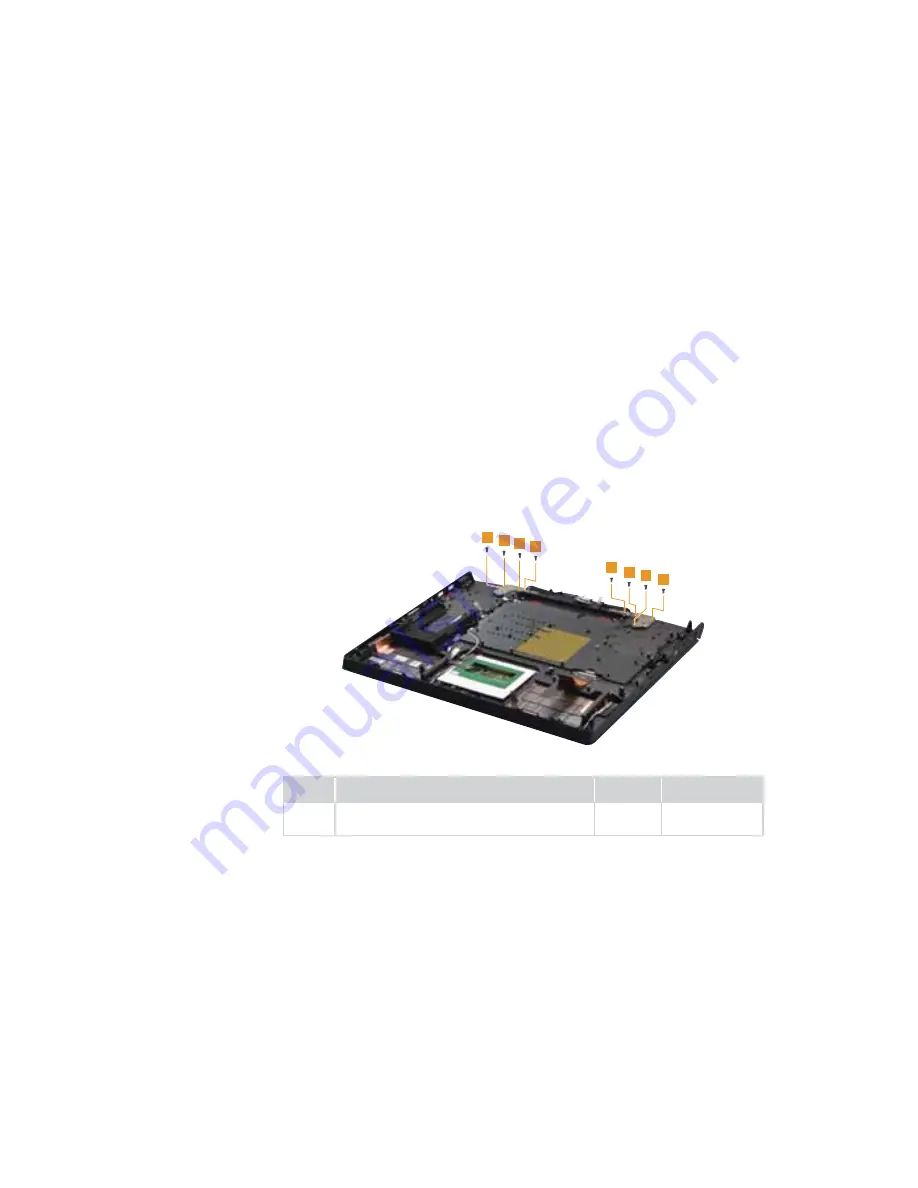
Figure 12. Removal steps of upper case

Remove the screws 

.

1

1

1

1

1

1

1

1

Step

Screw (quantity)

Color

Torque

0îPP3KLOOLSVKHDGQ\ORNFRDWHG

hinge to C Cover

black + 
blue

3.5 - 4.5 kg_cm

Summary of Contents for ideapad Y910-17ISK

Page 1: ...Lenovo ideapad Y910 17ISK Hardware Maintenance Manual ...

Page 2: ...ices on page 68 First Edition Sep 2016 Copyright Lenovo 2016 All rights reserved LIMITED AND RESTRICTED RIGHTS NOTICE If data or software is delivered pursuant a General Services Administration GSA contract use reproduction or disclosure is subject to restrictions set forth in Contract No GS 35F 05925 2016 Lenovo ...

Page 3: ...y 23 Restore of factory default 23 Passwords 24 Power on password 24 Hard disk password 24 Administrator password 24 Power management 25 Putting the computer to sleep or shutting it down 25 Putting your computer to sleep 25 Shutting down the computer 25 Lenovo ideapad Y910 17ISK 26 6SHFL FDWLRQV 26 Status indicators 28 Use keyboard shortcuts 29 FRU replacement notices 31 Screw notices 31 Removing ...

Page 4: ...ation guidelines and safety information required for servicing computers 7KH SURGXFW VSHFL F VHFWLRQ LQFOXGHV VHUYLFH UHIHUHQFH DQG SURGXFW VSHFL F parts information Important This manual is intended only for trained servicers who are familiar with Lenovo products Use this manual to troubleshoot problems effectively Before servicing a Lenovo product make sure to read all the information under Safe...

Page 5: ...ore you service a Lenovo ideapad Y910 17ISK computer General safety on page 2 Electrical safety on page 3 Safety inspection guide on page 5 Handling devices that are sensitive to electrostatic discharge on page 6 Grounding requirements on page 6 Safety notices multilingual translations on page 7 Laser compliance statement on page 14 ...

Page 6: ...afe place away from all personnel while you are servicing the machine Keep your toolcase away from walk areas so that other people will not trip over it Do not wear loose clothing that can be trapped in the moving parts of the machine Make sure that your sleeves are fastened or rolled up above your elbows If your hair is long fasten it Insert the ends of your necktie or scarf inside clothing or fa...

Page 7: ...x in the off position If you need to work on a machine that has exposed electrical circuits observe the following precautions Ensure that another person familiar with the power off controls is near you Attention Another person must be there to switch off the power if necessary Use only one hand when working with powered on electrical equipment keep the other hand in your pocket or behind your back...

Page 8: ...ace of a plastic dental mirror The surface is conductive such touching can cause personal injury and machine damage Do not service the following parts with the power on when they are removed from their normal operating places in a machine Power supply units Pumps Blowers and fans Motor generators and similar units This practice ensures correct grounding of the units If an electrical accident occur...

Page 9: ... or missing hardware To determine whether there are any potential unsafe conditions use the following checklist at the beginning of every service task Begin the checks with the power off and the power cord disconnected Checklist 1 Check exterior covers for damage loose broken or sharp edges 2 Turn off the computer Disconnect the power cord 3 Check the power cord for a A third wire ground connector...

Page 10: ...kin to eliminate static on your body Prevent the part from touching your clothing Most clothing is insulative and retains a charge even when you are wearing a wrist strap Use the black side of a grounded work mat to provide a static free work surface The mat is especially useful when handling ESD sensitive devices Select a grounding system such as those listed below to provide protection WKDW PHHW...

Page 11: ...RU Austausch der Computer wieder angeschlossen wird muß sichergestellt werden daß keine Schrauben Federn oder andere Kleinteile IHKOHQ RGHU LP HKlXVH YHUJHVVHQ ZXUGHQ HU RPSXWHU PX JHVFK WWHOW XQG DXI ODSSHUJHUlXVFKH JHSU IW ZHUGHQ 0HWDOOWHLOH RGHU VSOLWWHU N QQHQ XU VFKO VVH HU HXJHQ 3ULPD GL DFFHQGHUH O HODERUDWRUH GRSR FKH p VWDWD HIIHWWXDWD OD VRVWLWX LRQH GL XQD FRU accertarsi che tutte le vi...

Page 12: ...G DGPLXP HQWKDOWHQ 6LH GDUI QLFKW HUOHJW ZLHGHUDXIJHODGHQ NXU JHVFKORVVHQ RGHU HXHU RGHU DVVHU DXVJHVHW W ZHUGHQ HL GHU QWVRUJXQJ GLH UWOLFKHQ HVWLPPXQJHQ I U 6RQGHUP OO EHDFKWHQ HLP UVHW HQ GHU HUHLWVFKDIWV RGHU 6 VWHPEDWWHULH QXU DWWHULHQ GHV 7 SV YHUZHQGHQ GHU LQ GHU UVDW WHLOOLVWH DXIJHI KUW LVW HU LQVDW IDOVFKHU DWWHULHQ NDQQ X QW QGXQJ RGHU SORVLRQ I KUHQ OFXQH EDWWHULH GL ULVHUYD FRQWHQJRQR...

Page 13: ...GHQ NXU JHVFKORVVHQ RGHU HXHU RGHU DVVHU DXVJHVHW W ZHUGHQ HL GHU QWVRUJXQJ GLH UWOLFKHQ HVWLPPXQJHQ I U 6RQGHUP OO EHDFKWHQ HLP UVHW HQ GHU DWWHULH QXU DWWHULHQ GHV 7 SV YHUZHQGHQ GHU LQ GHU UVDW WHLOOLVWH DXIJHI KUW LVW HU LQVDW IDOVFKHU DWWHULHQ NDQQ X QW QGXQJ RGHU SORVLRQ I KUHQ D EDWWHULD FRQWLHQH SLFFROH TXDQWLWj GL QLFKHO 1RQ VPRQWDUOD JHWWDUOD QHO IXRFR R QHOO DFTXD Qp FRUWRFLUFXLWDUOD 6P...

Page 14: ...IHQ DWWHULHQ GLHVHV 7 SV G UIHQ QLFKW DXIJHODGHQ HUOHJW EHU HUKLW W RGHU YHUEUDQQW ZHUGHQ XFK GDUI LKU QKDOW QLFKW PLW DVVHU LQ 9HUELQGXQJ JHEUDFKW RGHU GHU XU ULFKWLJHQ 3ROXQJ DQJHEUDFKWH 9HUELQGXQJVVWHFNHU HQWIHUQW ZHUGHQ HL GHU QWVRUJXQJ GLH UWOLFKHQ HVWLPPXQJHQ I U 6RQGHUP OO EHDFKWHQ HLP UVHW HQ GHU DWWHULH QXU DWWHULHQ GHV 7 SV YHUZHQGHQ GHU LQ GHU UVDW WHLOOLVWH DXIJHI KUW LVW HU LQVDW IDOV...

Page 15: ...HVWHKW DXV ODV XQG NDQQ HUEUHFKHQ ZHQQ HU XQVDFKJHPl EHKDQGHOW ZLUG RGHU GHU RPSXWHU DXI GHQ RGHQ IlOOW HQQ GHU LOGVFKLUP EHVFKlGLJW LVW XQG GLH GDULQ EHILQGOLFKH O VVLJNHLW LQ RQWDNW PLW DXW XQG XJHQ JHUlW VROOWHQ GLH EHWURIIHQHQ 6WHOOHQ PLQGHVWHQV 0LQXWHQ PLW DVVHU DEJHVS OW XQG EHL HVFKZHUGHQ DQVFKOLH HQG HLQ U W DXIJHVXFKW ZHUGHQ 1HO FDVR FKH FDVR O VL GRYHVVH URPSHUH HG LO OLTXLGR LQ HVVR FRQ...

Page 16: ...unded battery can produce enough current to burn personnel or combustible materials Bien que le voltage des batteries principales soit peu élevé le court circuit ou la PLVH j OD PDVVH G XQH EDWWHULH SHXW SURGXLUH VXI VDPPHQW GH FRXUDQW SRXU EU OHU GHV PDWpULDX FRPEXVWLEOHV RX FDXVHU GHV EU OXUHV FRUSRUHOOHV JUDYHV 2EZRKO DXSWEDWWHULHQ HLQH QLHGULJH 6SDQQXQJ KDEHQ N QQHQ VLH GRFK EHL XU VFKOX RGHU ...

Page 17: ... HW GpFRQQHFWH WRXV OHV FRUGRQV G LQWHUIDFH LH 6WURP XIXKU PX DEJHVFKDOWHW DOOH 6WURPNDEHO DXV GHU 6WHFNGRVH JH RJHQ der Akku entfernt und alle Verbindungskabel abgenommen sein bevor eine FRU entfernt wird 3ULPD GL ULPXRYHUH TXDOVLDVL 58 VSHJQHUH LO VLVWHPD VFROOHJDUH GDOOH SUHVH HOHWWULFKH WXWWL L FDYL GL DOLPHQWD LRQH ULPXRYHUH OD EDWWHULD H SRL VFROOHJDUH L FDYL di interconnessione Antes de qui...

Page 18: ...WV RU SHUIRUPDQFH RI SURFHGXUHV RWKHU WKDQ WKRVH VSHFL HG KHUHLQ PLJKW UHVXOW LQ KD DUGRXV UDGLDWLRQ H SRVXUH 2 XVR GH FRQWUROHV DMXVWHV RX GHVHPSHQKR GH SURFHGLPHQWRV GLIHUHQWHV GDTXHOHV DTXL HVSHFL FDGRV SRGH UHVXOWDU HP SHULJRVD H SRVLomR j UDGLDomR 3RXU pYLWHU WRXW ULVTXH G H SRVLWLRQ DX UD RQ ODVHU UHVSHFWH OHV FRQVLJQHV GH réglage et d utilisation des commandes ainsi que les procédures décri...

Page 19: ...L H GH OX 5D RQQHPHQW ODVHU VL FDUWHU RXYHUW eYLWH GH IL HU OH IDLVFHDX GH OH UHJDUGHU GLUHFWHPHQW DYHF GHV LQVWUXPHQWV RSWLTXHV RX GH YRXV H SRVHU DX UD RQ DVHUVWUDKOXQJ EHL JH IIQHWHP HUlW 1LFKW GLUHNW RGHU EHU RSWLVFKH QVWUXPHQWH in den Laserstrahl sehen und den Strahlungsbereich meiden LQ LWiVNRU Op HUVXJiU 1H Qp HQ EHOH VH V DEDG V HPPHO VH RSWLNDL HV N NNHO HU OMH D VXJiUQ DOiEEDO YDOy pULQW...

Page 20: ...are posted on the customer support site KWWS VXSSRUW OHQRYR FRP Strategy for replacing FRUs Before replacing parts 0DNH VXUH WKDW DOO VRIWZDUH HV GULYHUV DQG 26 GRZQORDGV DUH LQVWDOOHG before replacing any FRUs listed in this manual After a system board is replaced ensure that the latest BIOS is loaded to the system board before completing the service action 7R GRZQORDG VRIWZDUH HV GULYHUV DQG 26 ...

Page 21: ... FRQ JXUDWLRQ VHWWLQJV XVLQJ WKH 9LHZ RQ JXUDWLRQ option then when service has been completed verify that those settings remain in effect Strategy for replacing a hard disk drive Always try to run a low level format before replacing a hard disk drive This will cause all customer data on the hard disk to be lost Make sure that the customer has a current backup of the data before performing this act...

Page 22: ...compliance well before the implementation date and expects its suppliers to be ready to support Lenovo s requirements and schedule in the EU Products sold in 2005 and 2006 will contain some RoHS compliant FRUs The following statement pertains to these products and any product Lenovo produces containing RoHS compliant FRUs RoHS compliant FRUs have unique FRU part numbers Before or after the RoHS im...

Page 23: ...PLJKW have been altered If you select an incorrect drive data or programs might be overwritten 5HSODFH DQ 58 RQO ZLWK DQRWKHU 58 RI WKH FRUUHFW PRGHO KHQ RX replace an FRU make sure that the machine model and the FRU part number are correct by referring to the FRU parts list Q 58 VKRXOG QRW EH UHSODFHG MXVW EHFDXVH RI D VLQJOH XQUHSURGXFLEOH IDLOXUH Single failures can occur for a variety of reaso...

Page 24: ... the warranty by referring to the following list The following are not covered under warranty LCD panel cracked from the application of excessive force or from being dropped Scratched cosmetic parts Distortion deformation or discoloration of the cosmetic parts Plastic parts latches pins or connectors that have been cracked or broken by excessive force Damage caused by liquid spilled into the syste...

Page 25: ...here because the computer fails only when the AC adapter is used If the power on indicator does not turn on check the power cord of the AC adapter for correct continuity and installation If the computer does not charge during operation go to Checking operational charging To check the AC adapter follow the steps below 1 Unplug the AC adapter cable from the computer 2 Measure the output voltage at t...

Page 26: ...ttery pack If it is still not charged go to the next section Checking the battery pack Battery charging does not start until the Power Meter shows that less than 95 of the total power remains under this condition the battery pack can charge to 100 of its capacity This protects the battery pack from being overcharged or from having a shortened life To check your battery move your cursor to the Powe...

Page 27: ... OneKey Recovery System In order to save application files and the initial backed up files of the system the hard disk in a Lenovo computer includes a hidden partition when it is shipped If you need to restore the system to the point of your first boot up just enter Lenovo OneKey Recovery System and run System Recovery For details of OneKey Recovery System see the Training Manual for Backup and re...

Page 28: ...rd disk passwords HDPs User HDP for the user Master HDP for the system administrator who can use it to get access to the hard disk drive even if the user has changed the user HDP Attention If the user HDP has been forgotten check whether a master HDP has been set If it has it can be used for access to the hard disk drive If no master HDP is available neither Lenovo nor Lenov authorized service tec...

Page 29: ...omputer to sleep do one of the following Close the display lid Press the Power button Open the start menu and then select Power o Sleep Attention Wait until the power indicator light starts blinking indicating that the computer is in sleep mode before you move your computer Moving your computer while the hard disk is spinning can damage the hard disk causing loss of data To wake the computer do on...

Page 30: ...r QWHO 6N ODNH PRELOH SURFHVVRU 7R FKHFN WKH PRGHO QDPH RI WKH SURFHVVRU LQVWDOOHG RQ RXU FRPSXWHU FOLFN 6WDUW ĺ 6HWWLQJV ĺ 6 VWHP ĺ ERXW UDSKLF PHPRU chip 7 0 Display LQFK î Standard PHPRU 5 62 00 î PD Hard disk drive LQFK PP 6 7 7 66 1 0 VORW î 7 2 SRUW 86 î 86 DOZD V RQ î 7 SH 86 î LVSOD 3RUW î 0 RXW î WKHUQHW SRUW î 0HPRU FDUG VORW LQ 6 6 6 00 00 3OXV 6 2 FDUG 86 ZLWK DOZD V RQ IHDWXUH 7KLV FR...

Page 31: ...reless 7 Keyboard 0HFKDQLFDO NH ERDUG Touchpad 0XOWL WRXFK W SH Integrated camera LJK GH QLWLRQ S Battery LWKLXP LRQ PEHGGHG FHOOV K 7KH FDSDFLW JLYHQ KHUH LV WKH W SLFDO RU DYHUDJH FDSDFLW as measured in a specific test environment Capacities measured in other environments may differ but are no lower than the rated capacity see product label AC adapter 9 GF Pre installed operating system 26 LQGRZ...

Page 32: ...er status 1 2 Table 2 Status indicators Indicator Indicator status Charge status Meaning Power On solid white The computer is powered on Blinking The computer is in sleep mode Off The computer is powered off dc in On solid white Connect the AC power adapter to the computer Off Disconnect the AC power adapter from the computer ...

Page 33: ...wn the Fn key and press one of the function keys Table 3 Shortcuts using the Fn key Key Function Disables enables the Windows key Note You may need to disable the Windows key during a gameplay Disables enables the touch pad Turns on off airplane mode Note When airplane mode is turned on all radio from and to Y910 17ISK is turned off Switches display devices Note You can connect external display de...

Page 34: ...ic keypad is disabled Note Press the Num Lk key to enable disable the numeric keypad The Led light on the key indicates whether the numeric keypad is enabled Table 4 Shortcuts with single keystrokes Key Function Starts Lenovo Magic Y Key Starts Lenovo Nerve Center Turns off on sound Decreases increases volume Disables enables the microphone Decreases increases the display brightness Decreases incr...

Page 35: ...emove screws for reuse when replacing FRUs Use a torque screwdriver if you have one Tighten screws as follows Plastic to plastic Turn an additional 90 after the screw head touches the surface of the plastic part more than 90 Cross section Logic card to plastic Turn an additional 180 after the screw head touches the surface of the logic card more than 180 Cross section Torque driver If you have a t...

Page 36: ...es and follow any of the notes that pertain to replacement For information about connecting and arranging internal cables see Locations on page 58 8 When replacing an FRU use the correct screw as shown in the procedures DANGER Before removing any FRU turn off the computer unplug all power cords from electrical outlets remove the battery pack and then disconnect any of the interconnecting cables At...

Page 37: ... and 1 2 3 1 1 1 1 1 1 1 1 1 2 Step Screw quantity Color Torque 0 î PP 3KLOOLSV KHDG Q ORN FRDWHG D Cover to C Cover black red 1 5 2 5 kg_cm 0 î PP 3KLOOLSV KHDG Q ORN FRDWHG D Cover to C Cover top black blue 1 5 2 5 kg_cm 0 î PP 3KLOOLSV KHDG Q ORN FRDWHG D Cover to C Cover black blue 1 5 2 5 kg_cm ...

Page 38: ...Manual LJXUH 5HPRYDO VWHSV RI EDVH FRYHU FRQWLQXHG Turn the computer over and then open the computer display Separate the base cover from the upper case in the direction shown by arrow 4 Remove the base cover in the directions shown by arrows and 5 6 5 ...

Page 39: ...ng label b Indonesia D side label c Wlan BT label label for Brazil label for Israel label for South Africa label for US CA TW d KCC label BIS label e OS label For some models you also need to apply one or two FCC labels Check the ROG EDVH FRYHU LI LW KDV RQH RU WZR ODEHOV QG GXSOLFDWHV RI WKHP LQ WKH label kit and apply them to the new base cover RU WKH ORFDWLRQ RI HDFK ODEHO UHIHU WR WKH IROORZLQ...

Page 40: ...U RXU FRPSXWHU Q RWKHU EDWWHU FRXOG LJQLWH RU H SORGH Figure 2 Removal steps of battery pack Unplug the battery connector in the direction shown by arrow then remove the screws Remove the battery pack 3 2 2 2 2 2 1 Step Screw quantity Color Torque 0 î PP 3KLOOLSV KHDG Q ORN FRDWHG battery to c black red 1 5 2 5 kg_cm When installing 0DNH VXUH WKDW WKH EDWWHU FRQQHFWRU LV DWWDFKHG UPO ...

Page 41: ... drive is sensitive to physical shock Improper handling can cause damage and permanent loss of data HIRUH UHPRYLQJ WKH GULYH VXJJHVW WKH FXVWRPHU WR EDFNXS DOO WKH LQIRUPDWLRQ RQ it if possible 1HYHU UHPRYH WKH GULYH ZKLOH WKH V VWHP LV RSHUDWLQJ RU LQ VXVSHQG PRGH Figure 3 Removal steps of solid state disk and hard disk drive Remove the screw 1 Step Screw quantity Color Torque 0 î PP 3KLOOLSV KHD...

Page 42: ... RI VROLG VWDWH GLVN DQG KDUG GLVN GULYH FRQWLQXHG Remove the solid state disk in the direction shown by arrow 2 Unplug the HDD connector and the IO board cable connector in the directions shown by arrows and 3 5 4 When installing 0DNH VXUH WKDW WKH FRQQHFWRUV DUH DWWDFKHG UPO ...

Page 43: ...ideapad Y910 17ISK LJXUH 5HPRYDO VWHSV RI VROLG VWDWH GLVN DQG KDUG GLVN GULYH FRQWLQXHG Lift the IO board cable in the direction shown by arrow Peel off the adhetive tape 6 7 7 7 7 7 Remove the HDD copper foil 8 ...

Page 44: ... GLVN GULYH FRQWLQXHG Remove the hard disk drive in the direction shown by arrow 9 Detach the cable from the hard disk drive in the direction shown by arrow 10 Note Aluminium foil is stuck on the HDD Do not use too much force when removing the aluminium foil otherwise it might be damaged during disassembly ...

Page 45: ...bers for the approved modules Figure 4 Removal steps of PCI Express Mini Card for wireless LAN Disconnect the two wireless LAN cables black white and then remove the screw 2 1 In step unplug the jacks by using the removal tool antenna RF connector 3 1 RU SLFN XS WKH FRQQHFWRUV ZLWK RXU QJHUV DQG JHQWO XQSOXJ them in the direction shown by the arrows Notes The wireless LAN card has 2 cables in step...

Page 46: ...ith a wireless LAN card that has two antenna connectors plug the black cable 1st MAIN into the jack labeled MAIN and the grey cable QG 8 LQWR WKH MDFN ODEHOHG AUX on the card In models with a wireless LAN card that has three antenna connectors plug the black cable 1st MAIN into the jack labeled 1 the grey cable 3rd into the jack labeled 3 DQG WKH ZKLWH FDEOH QG 8 LQWR WKH MDFN ODEHOHG 2 on the car...

Page 47: ...d then unplug the DIMM in the direction shown by arrow 2 1 1 Note If only one DIMM is used on the computer you are servicing the card must be installed in SLOT 0 a You can increase the amount of memory in the computer See illustration below in order of a b c d Side A Side B a b c d When installing Insert the notched end of the DIMM into the socket Push the 00 UPO DQG SLYRW LW XQWLO LW VQDSV LQWR S...

Page 48: ...eps of subwoofer Unplug the subwoofer connector in the direction shown by arrow Remove the screws Then remove the subwoofer in the direction shown by arrow 2 2 1 3 Note Be careful not to damage the connector Step Screw quantity Color Torque 0 î PP 3KLOOLSV KHDG Q ORN FRDWHG woofer Speaker to C Cover black blue 1 5 2 5 kg_cm When installing 0DNH VXUH WKDW WKH FRQQHFWRU LV DWWDFKHG UPO ...

Page 49: ...0 Battery pack on page 36 Figure 7 Removal steps of IO board Detach the connector in the directions shown by arrows and then remove the screws 2 1 3 3 3 3 Step Screw quantity Color Torque 0 î PP 3KLOOLSV KHDG Q ORN FRDWHG IO board to c black red 1 5 2 5 kg_cm Remove the IO board in the direction shown by arrow 4 ...

Page 50: ...Battery pack on page 36 Figure 8 Removal steps of fan assembly and heat sink assembly Unplug the fan connectors in the direction shown by arrows Remove the screws Then remove the two fans 1 1 3 3 2 2 2 2 2 2 Step Screw quantity Color Torque 0 î PP 3KLOOLSV KHDG Q ORN FRDWHG fan to c black red 1 5 2 5 kg_cm When installing 0DNH VXUH WKDW WKH FRQQHFWRUV DUH DWWDFKHG UPO ...

Page 51: ...ink assembly in the direction shown by arrow 4 4 5 4 4 4 4 a b When installing Before you attach the heat sink assembly to the computer apply thermal grease at an amount of 0 2 grams to the parts shown in WKH JXUH DERYH LWKHU WRR PXFK RU WRR OLWWOH JUHDVH DSSOLFDWLRQ FDQ FDXVH D thermal problem due to imperfect contact with a component ...

Page 52: ... VXUH QRW WR GURS RU VWDFN WKH V VWHP ERDUG I RX SXW D V VWHP ERDUG GRZQ PDNH VXUH WR SXW LW RQO RQ D SDGGHG VXUIDFH VXFK DV DQ 6 PDW RU FRQGXFWLYH FRUUXJDWHG PDWHULDO For access remove these FRUs in order 1010 Base cover on page 33 1020 Battery pack on page 36 1030 Solid state disk and hard disk drive on page 37 1040 PCI Express Mini Card for wireless LAN on page 41 1060 Subwoofer on page 44 1070...

Page 53: ...able connector the touch panel and touch panel lighting FFC connector KB FPC connector DC IN cable connector in the directions shown by arrows and 4 4 3 3 3 2 3 5 5 When installing 0DNH VXUH WKDW WKH FRQQHFWRUV DUH DWWDFKHG UPO Remove the screws 6 6 6 6 6 6 6 6 6 6 6 6 Step Screw quantity Color Torque 0 î PP 3KLOOLSV KHDG Q ORN FRDWHG MB to c black red 1 5 2 5 kg_cm ...

Page 54: ...SV RI V VWHP ERDUG FRQWLQXHG Remove the system board in the direction shown by arrow 7 Disconnect the RTC battery connector in the direction shown by arrow Remove the RTC battery in the direction shown by arrow 8 9 When installing 0DNH VXUH WKDW WKH FRQQHFWRU LV DWWDFKHG UPO ...

Page 55: ...less LAN on page 41 1060 Subwoofer on page 44 1070 IO board on page 45 1080 Fan assembly and Heat Sink assembly on page 46 1090 System board on page 48 Figure 10 Removal steps of speakers Release the cable from the cable guide and then remove the screws Remove the speakers in the direction shown by arrow 1 2 1 Step Screw quantity Color Torque 0 î PP 3KLOOLSV KHDG Q ORN FRDWHG R L speaker to C Cove...

Page 56: ... pack on page 36 1030 Solid state disk and hard disk drive on page 37 1040 PCI Express Mini Card for wireless LAN on page 41 1060 Subwoofer on page 44 1070 IO board on page 45 1080 Fan assembly and Heat Sink assembly on page 46 1090 System board on page 48 Figure 11 Removal steps of DC in cable Remove the DC in cable in the direction shown by arrow 1 ...

Page 57: ...ess Mini Card for wireless LAN on page 41 1060 Subwoofer on page 44 1070 IO board on page 45 1080 Fan assembly and Heat Sink assembly on page 46 1090 System board on page 48 1100 Speakers on page 51 1110 DC in cable on page 52 Figure 12 Removal steps of upper case Remove the screws 1 1 1 1 1 1 1 1 Step Screw quantity Color Torque 0 î PP 3KLOOLSV KHDG Q ORN FRDWHG hinge to C Cover black blue 3 5 4 ...

Page 58: ...Lenovo ideapad Y910 17ISK Hardware Maintenance Manual LJXUH 5HPRYDO VWHSV RI XSSHU FDVH FRQWLQXHG Open the hinge in the direction shown by arrows 2 2 Remove the upper case in the direction shown by arrow 3 ...

Page 59: ...0 IO board on page 45 1080 Fan assembly and Heat Sink assembly on page 46 1090 System board on page 48 1100 Speakers on page 51 1110 DC in cable on page 52 1120 Upper case on page 53 Figure 13 Removal steps of LCD unit Carefully remove the hinge cover in the direction shown by arrow 1 Remove the screws Remove the LCD module in the direction shown by arrow 2 2 2 3 Step Screw quantity Color Torque 0...

Page 60: ...ion shown by arrow Then remove the EDP cable in the direction shown by arrow 4 5 Lift the camera board a little in the direction shown by arrow Disconnect the camera connector in the direction shown by arrow Then remove the camera board Note The integrated camera is stuck on the top center of the LCD cover 6 7 Remove the camera cable 8 ...

Page 61: ...emove the screws 9 9 9 9 9 9 9 9 9 9 Step Screw quantity Color Torque 0 î PP 3KLOOLSV KHDG Q ORN FRDWHG Hinge to A Cover black blue 3 5 4 5 kg_cm Then remove the hinges in the direction shown by arrows 10 10 When installing 0DNH VXUH WKDW WKH FRQQHFWRUV DUH DWWDFKHG UPO ...

Page 62: ...ht side view Camera Microphone hole Display Speakers Power button Mechanical keyboard Turbo toggle Touch pad Kensington mini security slot USB 3 0 connectors Combo audio jack Microphone jack 0 Memory card slot 1 Power indicator 2 Novo button 1 2 3 4 7 6 8 4 2 9 5 14 13 12 11 10 15 ...

Page 63: ...lots intake Ventilation slots outlet Subwoofer Antennas not visible from the outside dc in jack dc in indicator Display port connector HDMI out connector Ethernet connector Type C USB connector USB 3 0 connector USB 3 0 connector always on 2 1 2 5 6 7 8 9 10 11 12 4 3 4 ...

Page 64: ...e 66 AC adapters on page 66 Screws on page 66 Power cords on page 67 Note DFK 58 LV DYDLODEOH IRU DOO W SHV RU PRGHOV XQOHVV VSHFL F W SHV RU PRGHOV DUH VSHFL HG Attention R QRW DWWHPSW WR UHSODFH DQ 58 RQ RXU RZQ I DQ 58 LV GDPDJHG FRQWDFW D HQRYR DXWKRUL HG VHUYLFHU RU D PDUNHWLQJ UHSUHVHQWDWLYH IRU UHSODFHPHQW RU UHSDLU 2QO TXDOL HG WHFKQLFLDQV FDQ LQVSHFW RU UHSDLU WKLV SURGXFW ...

Page 65: ...61 Lenovo ideapad Y910 17ISK Overall 1 3 5 7 c a 12 14 2 b 4 6 8 9 10 11 13 15 ...

Page 66: ...9 N 2 Upper Case L 80V1 W KB FR 5CB0M56067 N 2 Upper Case L 80V1 W KB GR 5CB0M56035 N 2 Upper Case L 80V1 W KB NL 5CB0M56051 N 2 Upper Case L 80V1 W KB HG 5CB0M56066 N 2 Upper Case L 80V1 W KB BE 5CB0M56045 N 2 Upper Case L 80V1 W KB ICE 5CB0M56033 N 2 Upper Case L 80V1 W KB SA 5CB0M56027 N 2 Upper Case L 80V1 W KB SW 5CB0M56034 N 2 Upper Case L 80V1 W KB BU 5CB0M56031 N 2 Upper Case L 80V1 W KBCZ...

Page 67: ...1 RAM MTA16ATF2G64H 2G3B1 SM30G16514 N 12 HDD HTS541010A7E630 7mm 5400rpm 1T HDD 16200658 N 12 HDD Seagate ST1000LM035 1T 2 5 7mm 5400rpm HDD 5H20L22184 N 12 63 67 PP 7 16200554 N 12 HDD TSB MQ02ABF100 6G 1TB 5H20G09709 N 12 HDD ST Rosewood2D 7mm 2TB HDD 5H20M37521 N 13 Y900 JBL Ody6 Slim Speaker 5SB0K04130 N 14 Battery Y Gaming SP AL14M6P21 11 1V90wh6cell bty 5B10H35531 N 14 Battery Y Gaming SP C...

Page 68: ...64 Lenovo ideapad Y910 17ISK Hardware Maintenance Manual LCD FRUs In Lenovo ideapad Y910 17ISK there are following types of LCDs 17 3 in FHD LED 2 1 3 5 7 4 6 ...

Page 69: ...FRU FRU no CRU ID 1 Hinge Cover L 80Q1 5CB0L22053 N 2 LCD Module L 80V1 FHD 5D10M56052 N 3 Camera L 80V1 HD W 2MIC 5C20M77788 N 4 Camera Cable L 80Q1 5C10L22062 N 5 EDP Cable L 80V1 FHD 5C10M56047 N 6 Hinge L 80Q1 L R 5H50L22124 N 7 LCD Cover L 80Q1 5CB0L22061 N ...

Page 70: ...adapters Table 8 Parts list 3 pin AC adapters FRU P N CRU ID Adapter Delta ADL230NDC3A 20V11 5A adapter 5A10H28357 Adapter Liteon ADL230NLC3A 20V11 5A adapter 5A10H28356 Screws Table 9 Parts list Screws FRU P N CRU ID Screw L 80Q1 2 0D 2 0L K 7 0D 0 5T 5S10L22121 N Screw L 80Q1 2 0D 5 5L K 4 5D 0 8T 5S10L22076 N Screw L 80Q1 2D 10 9L K 3 5D 0 5T 5S10L22044 N Screw L 80Q1 2 0D 3 3L K 6 0D 0 7T 5S10...

Page 71: ...Switzerland 3 pin 0 3 121 8 SL60K75046 Brazil 3 pin 5 0 3 121 8 SL60K75049 Israel 3 pin 0 3 121 8 SL60K75043 US 3 pin 86 0 3 121 8 SL60K75021 Thailand 3 pin 7 0 3 121 8 SL60K75065 UK 3 pin 0 3 121 8 SL60K75040 India 3 pin 1 0 3 121 8 SL60K75037 Italy 3 pin 7 0 3 121 8 SL60K75064 Australia 3 pin 8 0 3 121 8 SL60K75058 Taiwan 3 pin 7 0 3 121 8 SL60K75034 Japan 3 pin 3 QWL 75 0 3 121 8 SL60K75015 Afr...

Page 72: ...hanges in the product s and or the program s described in this publication at any time without notice The products described in this document are not intended for use in implantation or other life support applications where malfunction may result in injury or death to persons The information contained in this document does not DIIHFW RU FKDQJH HQRYR SURGXFW VSHFL FDWLRQV RU ZDUUDQWLHV 1RWKLQJ LQ W...

Page 73: ...demarks of Lenovo in the United States other countries or both Lenovo OneKey ideapad Microsoft and Windows are trademarks of Microsoft Corporation in the United States other countries or both Other company products or service names may be trademarks or service marks of others ...

Reviews: