


Lenovo G410s Touch/G510s Touch Hardware Maintenance Manual
74
1190 Antenna assembly and LCD cover
For access, remove these FRUs in order:
• “1010 Battery pack” on page 35
• “1020 Dummy card” on page 36
• “1030 Hard disk drive(HDD)/Memory/Mini PCI Express Card slot
compartment cover” on page 37
• “1040 Hard disk drive” on page 38
• “1050 Optical drive” on page 41
• “1060 DIMM” on page 43
• “1070 PCI Express Mini Card for wireless LAN/WAN” on page 44
• “1080 Fan assembly” on page 46
• “1090 Keyboard” on page 47
• “1100 Keyboard bezel” on page 52
• “1110 System board” on page 55
• “1150 Base cover, speakers, USB and power assembly” on page 65
• “1160 LCD front bezel” on page 70
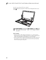
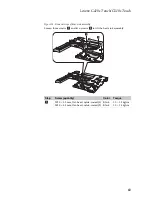
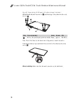
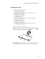
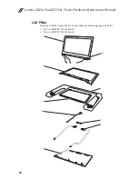
Figure 19. Removal steps of antenna assembly and LCD cover
Peel off the adhesive tapes securing the antenna boards, release the cables from
the cable guide, and then remove the antenna assembly in the direction shown
by arrows
.
When installing:
Route the antenna cables along the cable guides and secure the
antenna boards with adhesive tapes. As you route the cables, make sure that they
are not subjected to any tension. Tension could cause the cables to be damaged
by the cable guides, or a wire to be broken.
a
a
a


