


2.
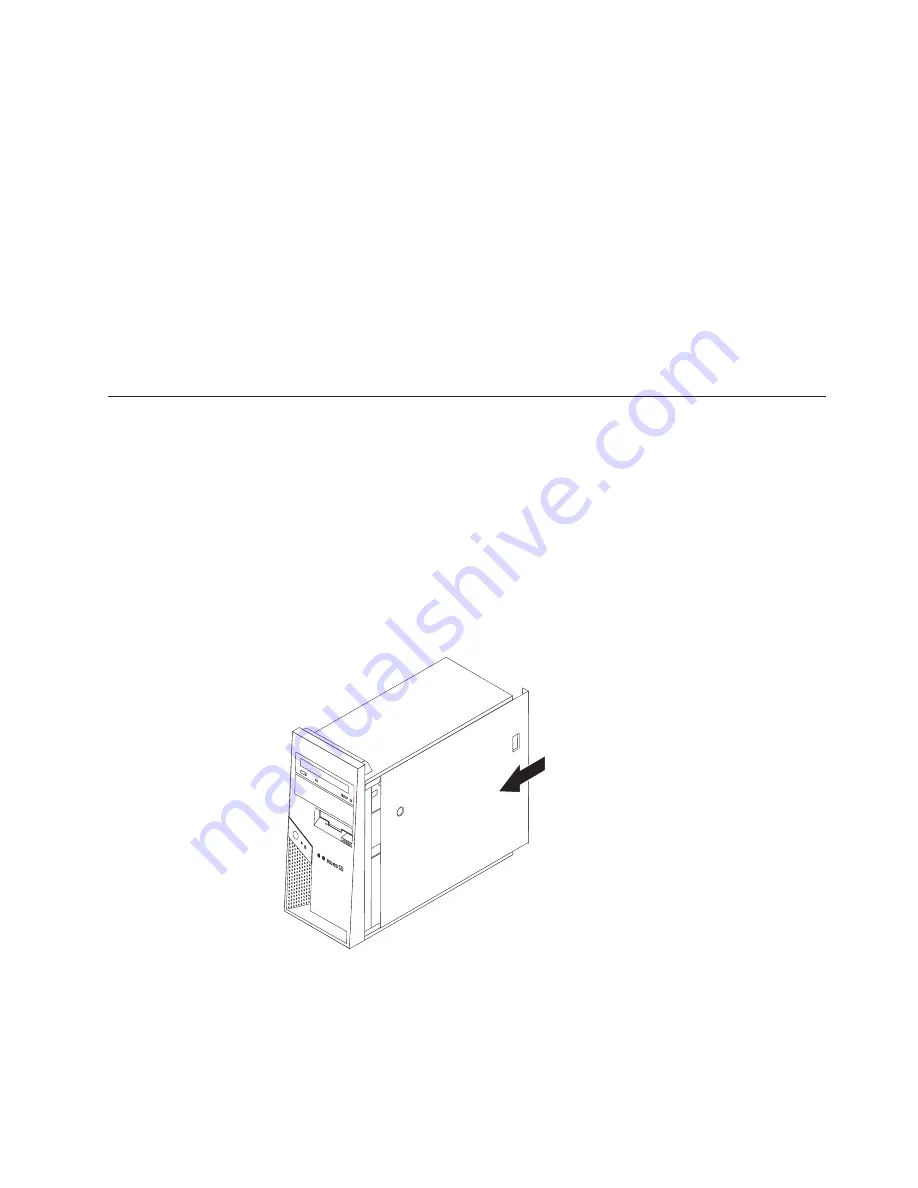
Remove
the
cover.
See
“Removing
the
cover”
on
page
10.
3.
Locate
the
Clear
CMOS/Recovery
jumper
on
the
system
board.
See
“Identifying
parts
on
the
system
board”
on
page
14.
4.
Move
the
jumper
from
the
standard
position
(pins
1
and
2)
to
the
maintenance
or
configure
position
(pins
2
and
3).
5.
Replace
the
cover
and
connect
the
power
cord.
See
“Replacing
the
cover
and
connecting
the
cables.”
6.
Restart
the
computer,
leave
it
on
for
approximately
ten
seconds.
Turn
off
the
computer
by
holding
the
power
switch
for
approximately
five
seconds.
The
computer
will
turn
off.
7.
Repeat
steps
2
through
4
on
page
27..
8.
Move
the
jumper
back
to
the
standard
(pins
1
and
2).
9.
Replace
the
cover
and
connect
the
power
cord.
See
“Replacing
the
cover
and
connecting
the
cables.”
Replacing
the
cover
and
connecting
the
cables
After
working
with
options,
you
need
to
install
any
removed
parts,
replace
the
cover,
and
reconnect
any
cables,
including
telephone
lines
and
power
cords.
Also,
depending
on
the
option
that
is
installed,
you
might
need
to
confirm
the
updated
information
in
the
Setup
Utility
program.
To
replace
the
cover
and
connect
cables
to
your
computer:
1.
Ensure
that
all
components
have
been
reassembled
correctly
and
that
no
tools
or
loose
screws
are
left
inside
your
computer.
2.
Clear
any
cables
that
might
impede
the
replacement
of
the
cover.
3.
Position
the
cover
on
the
chassis
so
that
the
rail
guides
on
the
bottom
of
the
cover
engage
the
rails
and
push
the
cover
closed
until
it
latches.
4.
Install
any
cover
locking
devices
such
as
a
cable
lock
or
padlock
as
necessary.
5.
Reconnect
the
external
cables
and
power
cords
to
the
computer.
See
“Installing
external
options”
on
page
6.
6.
To
update
the
configuration,
see
Chapter
2,
“Using
the
Setup
Utility
program,”
on
page
29.
Chapter
1.
Installing
options
27
Summary of Contents for 8113D5U
Page 1: ...User Guide Types 8110 8112 8113 8114 8115 Types 8153 8166 8167 8168 8169 8170 ...
Page 2: ......
Page 3: ...User Guide Types 8110 8112 8113 8114 8115 Types 8153 8166 8167 8168 8169 8170 ...
Page 6: ...iv User Guide ...
Page 16: ...xiv User Guide ...
Page 44: ...28 User Guide ...
Page 62: ...46 User Guide ...
Page 67: ......
Page 68: ...Part Number 39J8186 Printed in USA 1P P N 39J8186 ...


