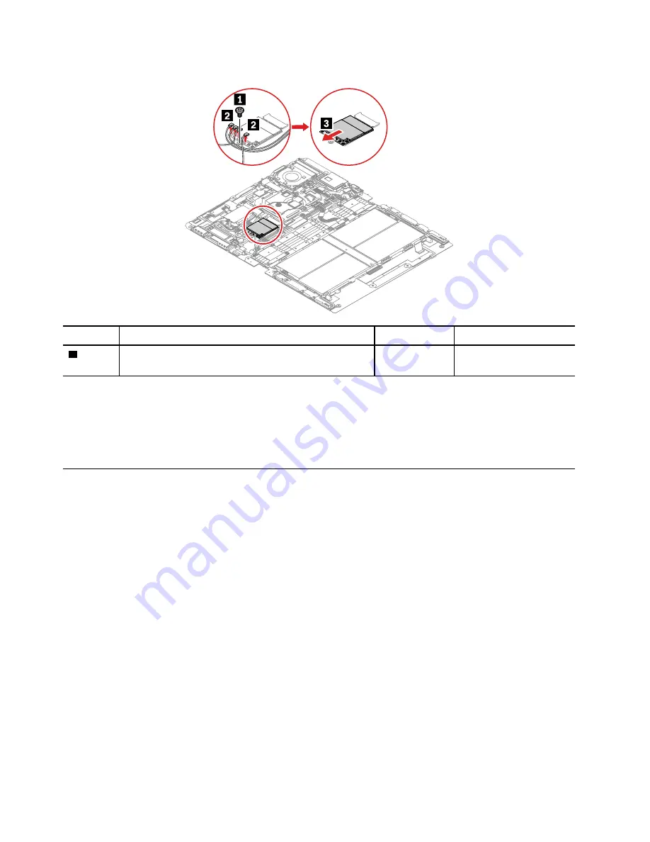
Removal steps of the wireless WAN card
Step
Screw (quantity)
Color
Torque
1
M1.6 × L1.85 mm, flat-head, nylon-coated (1)
Black
0.098 Nm
(1.0 kgf-cm)
When installing:
• Before you install a new wireless WAN card, apply a new thermal pad.
• Ensure that you connect the orange cable to the main connector, the blue cable to the auxiliary connector,
the white and grey cable to the M1 connector, and the black and grey cable to the M2 connector.
1090 USB-C sub cards and USB-C sub card cable
Before you replace the USB-C sub cards and USB-C sub card cable, do the following:
1. Disable the built-in battery. See “Disabling the built-in battery” on page 42.
2. Remove the Nano-SIM-card tray. See “Removing the Nano-SIM-card tray” on page 42.
3. Remove the following FRUs:
• “1010 Folio cover set” on page 43
• “1020 Smart glass and adhesive tapes” on page 47
• “1030 Access door” on page 49
• “1040 Support bracket” on page 49
• “1050 System board assembly ” on page 50
58
Hardware Maintenance Manual
Summary of Contents for 20RK
Page 1: ...Hardware Maintenance Manual ...
Page 4: ...ii Hardware Maintenance Manual ...
Page 6: ...iv Hardware Maintenance Manual ...
Page 11: ...DANGER DANGER DANGER DANGER DANGER Chapter 1 Safety information 5 ...
Page 12: ...DANGER DANGER 6 Hardware Maintenance Manual ...
Page 13: ...PERIGO Chapter 1 Safety information 7 ...
Page 14: ...PERIGO PERIGO PERIGO PERIGO 8 Hardware Maintenance Manual ...
Page 15: ...PERIGO PERIGO PERIGO DANGER DANGER Chapter 1 Safety information 9 ...
Page 16: ...DANGER DANGER DANGER DANGER DANGER 10 Hardware Maintenance Manual ...
Page 17: ...DANGER VORSICHT VORSICHT VORSICHT VORSICHT Chapter 1 Safety information 11 ...
Page 18: ...VORSICHT VORSICHT VORSICHT VORSICHT 12 Hardware Maintenance Manual ...
Page 19: ...Chapter 1 Safety information 13 ...
Page 20: ...14 Hardware Maintenance Manual ...
Page 21: ...Chapter 1 Safety information 15 ...
Page 22: ...16 Hardware Maintenance Manual ...
Page 23: ...Chapter 1 Safety information 17 ...
Page 24: ...18 Hardware Maintenance Manual ...
Page 25: ...Chapter 1 Safety information 19 ...
Page 26: ...20 Hardware Maintenance Manual ...
Page 34: ...28 Hardware Maintenance Manual ...
Page 40: ...34 Hardware Maintenance Manual ...
Page 67: ...Chapter 7 Removing or replacing a FRU 61 ...
Page 68: ...62 Hardware Maintenance Manual ...
Page 73: ......
Page 74: ...Part Number SP40G76967 Printed in China 1P P N SP40G76967 ...
Page 75: ... 1PSP40G76967 ...