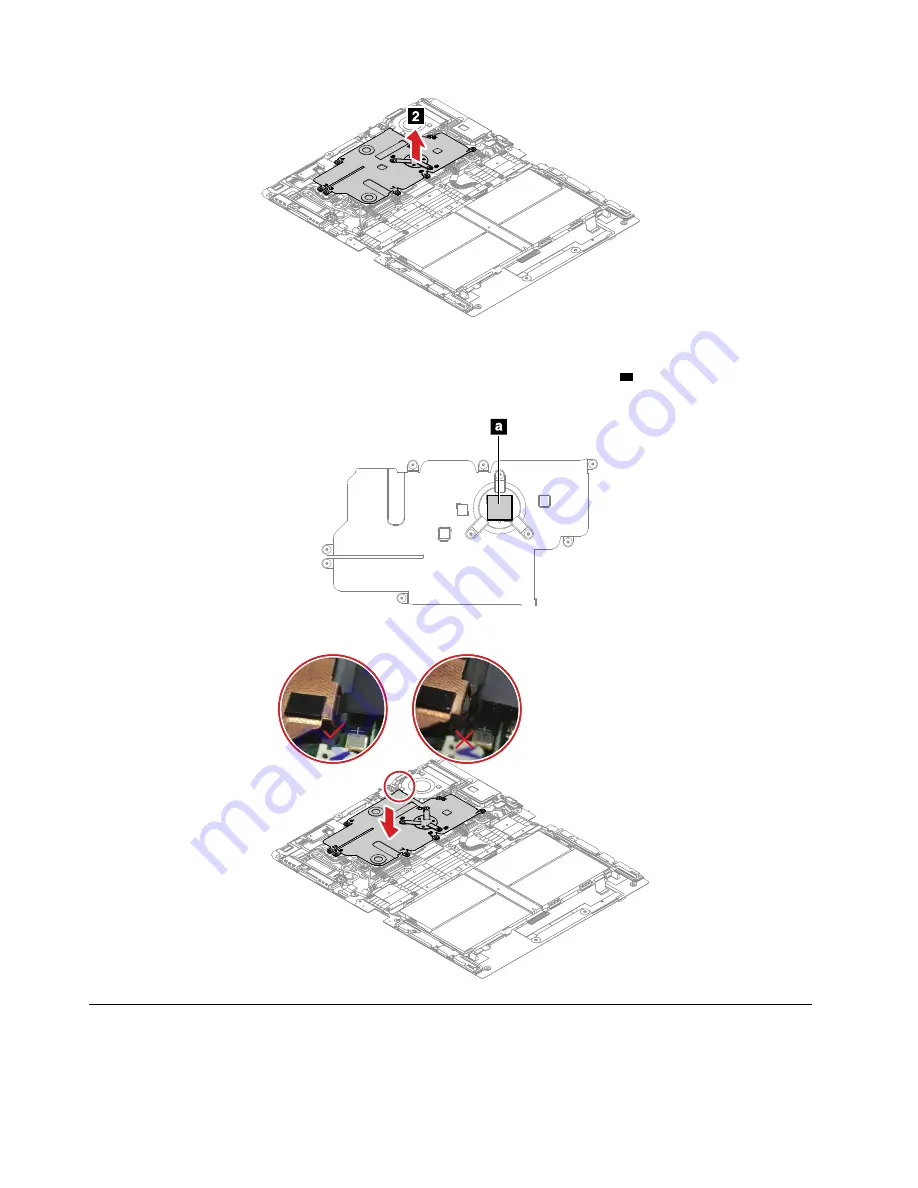
background image

When installing:  

•  Before you install a new thermal sub-spreader, apply the thermal pad on part 

as shown in the following 

illustration.  

•  Ensure that hook is latched correctly as shown in the following illustration. 

1070 M.2 solid-state drive

Before you replace the M.2 solid-state drive, do the following:  

1.  Disable the built-in battery. See “Disabling the built-in battery” on page 42.

56 

Hardware Maintenance Manual

Summary of Contents for 20RK

Page 1: ...Hardware Maintenance Manual ...

Page 2: ...er Appendix A Notices on page 63 First Edition September 2020 Copyright Lenovo 2020 LIMITED AND RESTRICTED RIGHTS NOTICE If data or software is delivered pursuant to a General Services Administration GSA contract use reproduction or disclosure is subject to restrictions set forth in Contract No GS 35F 05925 ...

Page 3: ...your computer 29 Recovering your operating system if Windows 10 fails to start 29 Creating and using a recovery USB drive 29 Lenovo factory recovery USB key 30 Using passwords 30 Symptom to FRU index 31 Numeric error codes 32 Intermittent problems 32 Undetermined problems 33 Chapter 5 Locations 35 Overview 35 Locating FRUs and CRUs 35 Major FRUs and CRUs 36 Other parts 38 Looking up FRU informatio...

Page 4: ...ii Hardware Maintenance Manual ...

Page 5: ...portant This manual is intended only for trained service technicians who are familiar with ThinkPad products Use this manual along with the advanced diagnostic tests to troubleshoot problems effectively Before servicing a ThinkPad product be sure to read all the information under Chapter 1 Safety information on page 1 and Chapter 2 Important service information on page 21 Copyright Lenovo 2020 iii...

Page 6: ...iv Hardware Maintenance Manual ...

Page 7: ...pment unsafe Before you start the machine make sure that other service technicians and the customer s personnel are not in a hazardous position Place removed covers and other parts in a safe place away from all personnel while you are servicing the machine Keep your toolcase away from walk areas so that other people will not trip over it Do not wear loose clothing that can be trapped in the moving...

Page 8: ...cur only when there is a complete circuit By observing the above rule you may prevent a current from passing through your body When using testers set the controls correctly and use the approved probe leads and accessories for that tester Stand on suitable rubber mats obtained locally if necessary to insulate you from grounds such as metal floor strips and machine frames Observe the special safety ...

Page 9: ...ry For the instruction on how to disable the built in battery see Disabling the built in battery on page 42 4 Disconnect the power cord 5 Check the power cord for the following a Make sure that a third wire ground connector is in good condition Use a meter to measure the third wire ground continuity Ensure that the continuity between the external ground pin and the frame ground is 0 1 ohm or less ...

Page 10: ...provide protection that meets the specific service requirement Note The use of a grounding system to guard against ESD damage is desirable but not necessary Attach the ESD ground clip to any frame ground ground braid or green wire ground When working on a double insulated or battery operated system use an ESD common ground or reference point You can use coax or connector outside shells on these sy...

Page 11: ...DANGER DANGER DANGER DANGER DANGER Chapter 1 Safety information 5 ...

Page 12: ...DANGER DANGER 6 Hardware Maintenance Manual ...

Page 13: ...PERIGO Chapter 1 Safety information 7 ...

Page 14: ...PERIGO PERIGO PERIGO PERIGO 8 Hardware Maintenance Manual ...

Page 15: ...PERIGO PERIGO PERIGO DANGER DANGER Chapter 1 Safety information 9 ...

Page 16: ...DANGER DANGER DANGER DANGER DANGER 10 Hardware Maintenance Manual ...

Page 17: ...DANGER VORSICHT VORSICHT VORSICHT VORSICHT Chapter 1 Safety information 11 ...

Page 18: ...VORSICHT VORSICHT VORSICHT VORSICHT 12 Hardware Maintenance Manual ...

Page 19: ...Chapter 1 Safety information 13 ...

Page 20: ...14 Hardware Maintenance Manual ...

Page 21: ...Chapter 1 Safety information 15 ...

Page 22: ...16 Hardware Maintenance Manual ...

Page 23: ...Chapter 1 Safety information 17 ...

Page 24: ...18 Hardware Maintenance Manual ...

Page 25: ...Chapter 1 Safety information 19 ...

Page 26: ...20 Hardware Maintenance Manual ...

Page 27: ...replacing any FRUs listed in this manual After a system board is replaced ensure that the latest UEFI BIOS is loaded to the system board before completing the service action To download software fixes drivers and UEFI BIOS go to https support lenovo com and follow the instructions on the screen If you are instructed to replace a FRU but the replacement does not correct the problem reinstall the or...

Page 28: ...s WW example 20AACTO1WW Special bid model This model is a unique configuration that has been negotiated between Lenovo and the customer A unique MTM consists of a 4 character MT a 4 character model and a numeric 2 character country code is provided to the customer to place orders example 20AA000955 The country code assigned is numeric and does not designate a specific country or region The custom ...

Page 29: ... in the parts exchange form or parts return form that you attach to it 1 Name and phone number of service technician 2 Date of service 3 Date on which the machine failed 4 Date of purchase 5 Failing FRU name and part number 6 Machine type model number and serial number 7 Customer s name and address Note During the warranty period the customer may be responsible for repair costs if the computer dam...

Page 30: ... the hardware scan function It combines diagnostic tests system information collection security status and support information along with hints and tips for optimal system performance Note If you are unable to isolate and repair the problem yourself after running the program save and print the log files created by the program You need the log files when you speak to a Lenovo technical support repr...

Page 31: ... error code descriptions and troubleshooting hints 2 Follow the instructions on the screen to use the diagnostic program The options on the main screen are as follows Note The items on the main screen of the UEFI diagnostic program are subject to change Table 1 Items on the main screen of the UEFI diagnostic program Tests Tools Quick Memory Test Quick Storage Device Test LCD test PCI e test Exit A...

Page 32: ... off the computer 6 Disconnect the ac power adapter and turn on the computer If the computer can be turned on it means that the battery is functional If you suspect a power problem see the appropriate one of the following power supply checkouts Checking the ac power adapter on page 26 Checking the built in battery and operational charging on page 27 Checking the ac power adapter You are here becau...

Page 33: ...tatus icon in the Windows notification area to check the battery status The battery status icon displays the percentage of battery power remaining and how long you can use your computer before you must charge the battery To check whether the battery charges properly during operation do the following 1 Discharge the battery until the remained battery power is less than 50 2 Connect the computer to ...

Page 34: ...28 Hardware Maintenance Manual ...

Page 35: ...te Security Recovery 2 In the Reset this PC section tap Get started 3 Follow the instructions on the screen to refresh your computer Recovering your operating system if Windows 10 fails to start The Windows recovery apps on your computer are capable of operating independently from the Windows 10 operating system This enables you to recover or repair the operating system even if the Windows 10 oper...

Page 36: ...factory recovery USB key enables you to reset your computer to the factory default settings To obtain a Lenovo factory recovery USB key contact Lenovo Customer Support Center Shipping and handling fees apply Telephone numbers for the Lenovo Support Center are available at https pcsupport lenovo com supportphonelist Note The Lenovo factory recovery USB key might not support certain operating system...

Page 37: ...iles and exit all apps 2 Restart the computer When the logo screen is displayed tap the prompt to display the Startup Interrupt Menu window In the Startup Interrupt Menu window tap F1 to enter the UEFI BIOS menu 3 Tap Security Password 4 Tap supervisor password and follow the instructions on the screen 5 Save configuration changes and exit Symptom to FRU index This section contains following infor...

Page 38: ...n a separate UEFI variable storage Press F1 after the error message is displayed to enter the UEFI BIOS menu A dialog asks for confirmation to clean up the storage If you select Yes all data that were created by the operating system or programs will be deleted except global variables defined by the Unified Extensible Firmware Interface Specification If you select No all data will be kept but the o...

Page 39: ...he computer 2 Visually check each FRU for damage Replace any damaged FRU 3 Remove or disconnect all of the following devices a Non ThinkPad devices b Devices attached to the docking station or the port replicator c Printer mouse and other external devices d Battery e External diskette drive or optical drive f PC cards 4 Turn on the computer 5 Determine whether the problem has been solved 6 If the ...

Page 40: ...34 Hardware Maintenance Manual ...

Page 41: ...mputer Overview Camera with infrared IR function Power button Volume button USB C connector USB 3 2 Gen 2 Nano SIM card tray for selected models Locating FRUs and CRUs This topic introduces the following service parts Major FRUs and CRUs on page 36 Other parts on page 38 Copyright Lenovo 2020 35 ...

Page 42: ...creen instructions to find the manual for your product You might be required to return the defective part that is replaced by the CRU When return is required 1 return instructions a prepaid shipping label and a container will be included with the replacement CRU and 2 you might be charged for the replacement CRU if Lenovo does not receive the defective CRU within thirty 30 days of your receipt of ...

Page 43: ...tem board assembly No No 5 Access door No No 6 Thermal sub spreader No No 7 Wireless WAN card No No 8 Thermal pad for wireless WAN card No No 9 M 2 solid state drive No No 10 Thermal pad for M 2 solid state drive No No 11 OLED assembly with frame cover and miscellaneous parts No No 12 USB C sub cards No No Chapter 5 Locations 37 ...

Page 44: ...els Other parts Table 2 Other parts Descriptions Self service CRU Optional service CRU Lenovo USB C to Ethernet Adapter Yes No Lenovo Pen Pro Yes No Lenovo Mod Pen Yes No Lenovo Fold Mini Keyboard Yes No Lenovo Powered USB C Travel Hub Yes No for selected models Looking up FRU information For detailed FRU information including part numbers descriptions and substitution part numbers go to https sup...

Page 45: ...ght be required to return the defective part that is replaced by the CRU When return is required 1 return instructions a prepaid shipping label and a container will be included with the replacement CRU and 2 you might be charged for the replacement CRU if Lenovo does not receive the defective CRU within thirty 30 days of your receipt of the replacement CRU See your Lenovo Limited Warranty document...

Page 46: ...Logic card to plastic Turn an additional 180 degrees after the screw head touches the surface of the logic card Notes Ensure that you use the correct screw It is recommended to use new screws for replacements If you have a torque screwdriver tighten all screws firmly to the torque specified in the screw information table for each step Ensure that torque screwdrivers are calibrated correctly follow...

Page 47: ... the following general guidelines 1 Do not try to service any computer unless you have been trained and certified An untrained person runs the risk of damaging parts 2 Before replacing any FRU review Chapter 6 FRU replacement notices on page 39 3 Begin by removing any FRUs that have to be removed before replacing the failing FRU Any such FRUs are listed at the beginning of in each FRU replacement ...

Page 48: ...k Change settings that are currently unavailable at the top 4 If prompted by User Account Control UAC click Yes 5 Clear the Turn on fast startup check box and then click Save changes To disable the built in battery do the following 1 Restart the computer When the logo screen is displayed tap the prompt to display the Startup Interrupt Menu window In the Startup Interrupt Menu window tap F1 to ente...

Page 49: ...the built in battery on page 42 2 Remove the Nano SIM card tray See Removing the Nano SIM card tray on page 42 Removal steps of the folio cover set Before releasing the adhesive tapes put a plastic plate between the folio cover set and system board assembly as shown in step 2 to protect both folio cover set and system board assembly In step 3 and step 4 use a tweezer to grab the tapes then roll th...

Page 50: ... all the screws in step 6 use a spudger or a pry tool to push the two slider brackets as shown in step 7 Step Screw quantity Color Torque 6 M2 L3 mm flat head nylon coated 4 Silver 0 181 Nm 1 85 kgf cm 44 Hardware Maintenance Manual ...

Page 51: ... steps of the folio cover set Step Screw quantity Color Torque 2 M2 0 L1 9 mm flat head nylon coated 8 Pink 0 137 Nm 1 4 kgf cm Put the folio cover as shown in step 3 ensure that there is a 5 mm to 10 mm distance between the edge of the folio cover and the computer edge Chapter 7 Removing or replacing a FRU 45 ...

Page 52: ...ssembly and slide the folio cover as shown in step 4 until the hooks on the bottom of the folio cover are latched correctly Step Screw quantity Color Torque 6 M2 L3 mm flat head nylon coated 4 Silver 0 181 Nm 1 85 kgf cm 46 Hardware Maintenance Manual ...

Page 53: ...replace the speaker assembly do the following 1 Disable the built in battery See Disabling the built in battery on page 42 2 Remove the Nano SIM card tray See Removing the Nano SIM card tray on page 42 3 Remove the folio cover set See 1010 Folio cover set on page 43 Chapter 7 Removing or replacing a FRU 47 ...

Page 54: ...Removal steps of the smart glass and adhesive tapes When installing Ensure that the adhesive taps are attached firmly 48 Hardware Maintenance Manual ...

Page 55: ...s of the access door Step Screw quantity Color Torque 1 M2 L3 5 mm flat head nylon coated 2 Black 0 181 Nm 1 85 kgf cm 1040 Support bracket Before you replace the support bracket do the following 1 Disable the built in battery See Disabling the built in battery on page 42 2 Remove the Nano SIM card tray See Removing the Nano SIM card tray on page 42 3 Remove the following FRUs 1010 Folio cover set...

Page 56: ...port bracket is installed correctly 1050 System board assembly Before you replace the system board assembly do the following 1 Disable the built in battery See Disabling the built in battery on page 42 2 Remove the Nano SIM card tray See Removing the Nano SIM card tray on page 42 3 Remove the following FRUs 1010 Folio cover set on page 43 50 Hardware Maintenance Manual ...

Page 57: ...040 Support bracket on page 49 Removal steps of the system board assembly Step Screw quantity Color Torque 8 M2 L3 5 mm flat head nylon coated 13 Black 0 181 Nm 1 85 kgf cm 9 M1 6 L2 6 mm flat head nylon coated 2 Black 0 098 Nm 1 0 kgf cm Chapter 7 Removing or replacing a FRU 51 ...

Page 58: ...f cm It is recommended that you install two screws M2 L3 5 mm in the two slots as shown in step 12 Recommended screw torque is 0 098 Nm 1 0 kgf cm This will help you remove the system board assembly easily When installing Ensure that the springs on system board assembly the are fixed correctly as shown in the following illustration 52 Hardware Maintenance Manual ...

Page 59: ... that the battery cable is under the tape tab as shown in the following illustration Ensure that all cables are routed correctly as shown in the following illustration Chapter 7 Removing or replacing a FRU 53 ...

Page 60: ...the country or region of delivery the labels might be slightly different from the ones in the following illustration The following illustration shows the location of each label Labels behind the kickstand 54 Hardware Maintenance Manual ...

Page 61: ...ollowing 1 Disable the thermal sub spreader See Disabling the built in battery on page 42 2 Remove the Nano SIM card tray See Removing the Nano SIM card tray on page 42 3 Remove the following FRUs 1010 Folio cover set on page 43 1020 Smart glass and adhesive tapes on page 47 1030 Access door on page 49 1040 Support bracket on page 49 1050 System board assembly on page 50 Removal steps of the therm...

Page 62: ... in the following illustration Ensure that hook is latched correctly as shown in the following illustration 1070 M 2 solid state drive Before you replace the M 2 solid state drive do the following 1 Disable the built in battery See Disabling the built in battery on page 42 56 Hardware Maintenance Manual ...

Page 63: ...d 1 Black 0 098 Nm 1 0 kgf cm When installing Before you install a new M 2 solid state drive apply a new thermal pad 1080 Wireless WAN card Before you replace the wireless WAN card do the following 1 Disable the built in battery See Disabling the built in battery on page 42 2 Remove the Nano SIM card tray See Removing the Nano SIM card tray on page 42 3 Remove the following FRUs 1010 Folio cover s...

Page 64: ...or and the black and grey cable to the M2 connector 1090 USB C sub cards and USB C sub card cable Before you replace the USB C sub cards and USB C sub card cable do the following 1 Disable the built in battery See Disabling the built in battery on page 42 2 Remove the Nano SIM card tray See Removing the Nano SIM card tray on page 42 3 Remove the following FRUs 1010 Folio cover set on page 43 1020 ...

Page 65: ...b card cable Step Screw quantity Color Torque 4 M2 L2 mm flat head nylon coated 4 Yellow 0 137 Nm 1 4 kgf cm When installing Ensure that you route the USB C sub card cable as shown in the following illustration Chapter 7 Removing or replacing a FRU 59 ...

Page 66: ...FRUs 1010 Folio cover set on page 43 1020 Smart glass and adhesive tapes on page 47 1030 Access door on page 49 1040 Support bracket on page 49 1050 System board assembly on page 50 1090 USB C sub cards and USB C sub card cable on page 58 When installing Before you install a new OLED assembly do not fold the screen as shown in the following illustration otherwise the nail could be damaged Apply sp...

Page 67: ...Chapter 7 Removing or replacing a FRU 61 ...

Page 68: ...62 Hardware Maintenance Manual ...

Page 69: ...ublication Lenovo may make improvements and or changes in the product s and or the program s described in this publication at any time without notice The products described in this document are not intended for use in implantation or other life support applications where malfunction may result in injury or death to persons The information contained in this document does not affect or change Lenovo...

Page 70: ...ited States other countries or both Lenovo Lenovo logo ThinkPad ThinkPad logo Thunderbolt is a trademark of Intel Corporation or its subsidiaries in the U S and or other countries Microsoft and Windows are trademarks of the Microsoft group of companies USB C is a trademark of USB Implementers Forum Other company product or service names may be trademarks or service marks of others 64 Hardware Main...

Page 71: ...CA Engineering Change Announcements EEPROM Electrically Erasable Programmable Read Only Memory EFI Extensible Firmware Interface EPO emergency power off ESD electrostatic discharge EU European Union FCC Federal Communications Commission FRU Field Replaceable Unit GAV General Announce Variant GPU graphics processing unit HDD hard disk drive HDMI high definition multimedia interface ICs integrated c...

Page 72: ...tor RJ registered jack SATA Serial Advanced Technology Attachment SIM subscriber identity module SVP supervisor password TFTs thin film transistors UEFI Unified Extensible Firmware Interface USB Universal Serial Bus UUID universally unique identifier VGA video graphics array VRAM video random access memory 66 Hardware Maintenance Manual ...

Page 73: ......

Page 74: ...Part Number SP40G76967 Printed in China 1P P N SP40G76967 ...

Page 75: ... 1PSP40G76967 ...

Reviews: