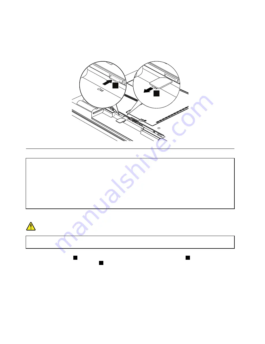
If the computer you are servicing has the SIM card, remove it before you start the servicing.
To remove the SIM card, you need to remove the battery pack first. (See “1010 Battery pack” on page 56.)
After you finish the servicing, make sure that you insert the card back into the slot firmly.
1
2
1010 Battery pack
Important notice for replacing a battery pack:
• Lenovo ThinkVantage Toolbox or Lenovo Solution Center ( in Windows 7) has an automatic battery diagnostic that
determines if the battery pack is defective. A battery pack FRU should not be replaced unless this diagnostic
shows that the battery is defective.
• The only exception to this is if the battery pack is physically damaged or a customer is reporting a possible
safety issue.
• If Lenovo ThinkVantage Toolbox is not installed in the computer, the customer should download this program
before a non-physically damaged battery pack is replaced. Note that the replacement of a physically damaged
battery pack is not covered by the warranty.
Removal steps of battery pack
DANGER
Use only the battery specified in the parts list for your computer. Any other battery could ignite
or explode.
Unlock the battery latch
1
. Holding the battery lock lever in the unlocked position
2
, remove the battery
pack in the direction shown by arrow
3
.
56
Hardware Maintenance Manual
Summary of Contents for 1141BUU
Page 1: ...Hardware Maintenance Manual ThinkPad Edge E420 and E425 ...
Page 6: ...iv Hardware Maintenance Manual ...
Page 11: ...DANGER DANGER DANGER DANGER DANGER Chapter 1 Safety information 5 ...
Page 12: ...DANGER 6 Hardware Maintenance Manual ...
Page 13: ...PERIGO PERIGO PERIGO Chapter 1 Safety information 7 ...
Page 14: ...PERIGO PERIGO PERIGO PERIGO PERIGO DANGER 8 Hardware Maintenance Manual ...
Page 15: ...DANGER DANGER DANGER DANGER DANGER Chapter 1 Safety information 9 ...
Page 16: ...DANGER DANGER VORSICHT VORSICHT VORSICHT 10 Hardware Maintenance Manual ...
Page 17: ...VORSICHT VORSICHT VORSICHT VORSICHT VORSICHT Chapter 1 Safety information 11 ...
Page 18: ...12 Hardware Maintenance Manual ...
Page 19: ...Chapter 1 Safety information 13 ...
Page 20: ...14 Hardware Maintenance Manual ...
Page 21: ...Chapter 1 Safety information 15 ...
Page 22: ...16 Hardware Maintenance Manual ...
Page 24: ...18 Hardware Maintenance Manual ...
Page 25: ...Chapter 1 Safety information 19 ...
Page 26: ...20 Hardware Maintenance Manual ...
Page 27: ...Chapter 1 Safety information 21 ...
Page 28: ...22 Hardware Maintenance Manual ...
Page 29: ...Chapter 1 Safety information 23 ...
Page 30: ...24 Hardware Maintenance Manual ...
Page 60: ...54 Hardware Maintenance Manual ...
Page 102: ...Overall 1 4 7 8 10 12 13 14 17 20 16 18 15 19 21 9 11 6 5 2 3 96 Hardware Maintenance Manual ...
Page 111: ...LCD FRUs 3 4 5 6 2 1 1 Chapter 10 Parts list 105 ...
Page 125: ......
Page 126: ...Part Number 0A60575_05 Printed in 1P P N 0A60575_05 1P0A60575_05 ...


