background image

DANGER

DANGER

DANGER

DANGER

Chapter 1

.

Safety information

5

Summary of Contents for 100S Chromebook-11IBY

Page 1: ...Hardware Maintenance Manual Lenovo 100S Chromebook 11IBY ...

Page 2: ......

Page 3: ...Hardware Maintenance Manual Lenovo 100S Chromebook 11IBY ...

Page 4: ...First Edition August 2015 Copyright Lenovo 2015 ...

Page 5: ...ving a FRU or CRU 25 General guidelines 25 Remove the upper case and the battery 25 Remove the I O board 28 Remove the WLAN Bluetooth combo module 29 Remove the speakers 30 Remove the system board and the DC in cable 31 Remove the touch pad module 33 Disassemble the LCD module 34 Remove the LCD bezel 34 Remove the LCD panel the hinges the LCD cable and the camera module 35 Appendix A Features cont...

Page 6: ...iv Hardware Maintenance Manual ...

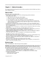
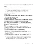
Page 7: ...e clothing or fasten it with a non conductive clip about 8 centimeters 3 inches from the end Do not wear jewelry chains metal frame eyeglasses or metal fasteners for your clothing Attention Metal objects are good electrical conductors Wear safety glasses when you are hammering drilling soldering cutting wire attaching springs using solvents or working in any other conditions that might be hazardou...

Page 8: ...efully for possible hazards in your work area Examples of these hazards are moist floors non grounded power extension cables power surges and missing safety grounds Do not touch live electrical circuits with the reflective surface of a plastic dental mirror The surface is conductive such touching can cause personal injury and machine damage Do not service the following parts with the power on when...

Page 9: ...d sensitive to electrostatic discharge ESD ESD damage can occur when there is a difference in charge between objects Protect against ESD damage by equalizing the charge so that the machine the part the work mat and the person handling the part are all at the same charge Notes 1 Use product specific ESD procedures when they exceed the requirements noted here 2 Make sure that the ESD protective devi...

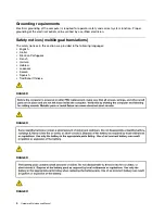
Page 10: ... the electrical outlet can be verified by a certified electrician Safety notices multilingual translations The safety notices in this section are provided in the following languages English Arabic Brazilian Portuguese French German Hebrew Japanese Korean Spanish Traditional Chinese DANGER DANGER DANGER DANGER 4 Hardware Maintenance Manual ...

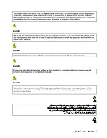
Page 11: ...DANGER DANGER DANGER DANGER Chapter 1 Safety information 5 ...

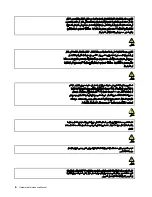
Page 12: ...6 Hardware Maintenance Manual ...

Page 13: ...PERIGO PERIGO PERIGO PERIGO Chapter 1 Safety information 7 ...

Page 14: ...PERIGO PERIGO PERIGO PERIGO DANGER DANGER 8 Hardware Maintenance Manual ...

Page 15: ...DANGER DANGER DANGER DANGER DANGER Chapter 1 Safety information 9 ...

Page 16: ...DANGER VORSICHT VORSICHT VORSICHT VORSICHT 10 Hardware Maintenance Manual ...

Page 17: ...VORSICHT VORSICHT VORSICHT VORSICHT Chapter 1 Safety information 11 ...

Page 18: ...12 Hardware Maintenance Manual ...

Page 19: ...Chapter 1 Safety information 13 ...

Page 20: ...14 Hardware Maintenance Manual ...

Page 21: ...Chapter 1 Safety information 15 ...

Page 22: ...16 Hardware Maintenance Manual ...

Page 23: ...Chapter 1 Safety information 17 ...

Page 24: ...18 Hardware Maintenance Manual ...

Page 25: ... nondefective FRU What to do first When you return a FRU you must include the following information in the parts exchange form or parts return form that you attach to it 1 Name and phone number of service technician 2 Date of service 3 Date on which the machine failed 4 Date of purchase 5 Failure symptoms error codes appearing on the display and beep symptoms 6 Procedure index and page number in w...

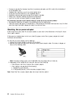
Page 26: ...mputer fails only when the ac power adapter is used refer to the information in this topic to check the ac power adapter If the power on indicator does not turn on check the power cord of the ac power adapter for correct continuity and installation To check the ac power adapter do the following 1 Unplug the ac power adapter cable from the computer 2 Measure the output voltage across the plug of th...

Page 27: ...rt numbers of replacement FRUs or CRUs on page 22 if you need to look up Lenovo part numbers for a particular FRU or CRU 1 2 3 8 9 4 5 6 7 Figure 1 Lenovo 100S Chromebook 11IBY exploded view Table 1 FRU CRU categories No FRU CRU category CRU ID 1 Upper case N 2 Battery pack N 3 System board N 4 Speakers N 5 DC in cable N 6 Lower case N 7 Touch pad module N 8 WLAN Bluetooth combo module N 9 I O boa...

Page 28: ...RU CRU category CRU ID 1 LCD bezel N 2 Hinges N 3 LCD panel N 4 LCD cable N 5 Camera module N 6 LCD base cover N Lenovo part numbers of replacement FRUs or CRUs When servicing a customer s computer Lenovo service technicians may use part numbers listed in the following tables to order replacement parts through Lenovo CRM customer relationship management system Table 3 Part numbers for FRUs CRUs No...

Page 29: ...ook N28404G32G 5B20K17769 MB Q 100S Chromebook N28402G32G 5B20K57706 4 Speakers Speaker Q 100S Chromebook 5SB0K11764 5 DC in cable DC IN Cable Q 100S Chromebook 5C10K11770 6 Lower case Lower Case Q 100S Chromebook 5CB0K11774 7 Touch pad module Touchpad ModuleQ100S Chromebook 5T60K11766 8 WLAN Bluetooth combo module Intel 7260 2x2AC BT PCIE M 2 WLAN V2 20200552 9 I O board IO BD Q 100S Chromebook W...

Page 30: ... AG S LED1 NB LCD 5D10H34460 BOE NT116WHM N21 HD AG S NB 5D10H34773 AUO B116XTN02 3 2B HD AG S NB 5D10H11015 4 LCD cable LCD Cable Q 100S Chromebook 5C10K11772 5 Camera module Camera Q 100S Chromebook 5C20K11765 6 LCD base cover LCD Cover Q 100S Chromebook BK 5CB0K11767 24 Hardware Maintenance Manual ...

Page 31: ...enovo 100S Chromebook 11IBY on page 41 for replacement screws and order them through the Lenovo CRM system 7 When replacing the base cover reapply all labels that come with the replacement base cover If some original labels are not included with the replacement base cover peal them off from the original base cover and paste them on the replacement base cover Refer to Appendix E Label locations on ...

Page 32: ...p 3 Use a pry bar to slide through the grooves between the upper case and the base cover 2 and then slowly lift the upper case until the keyboard socket appears 3 b a c Figure 4 Lift the upper case Step 4 Detach the battery connector 4 d Figure 5 Detach the battery connector 26 Hardware Maintenance Manual ...

Page 33: ...e Figure 6 Detach the touchpad cable and the keyboard cable Step 7 Remove the three screws 9 and then remove the battery pack in the direction shown by arrow 10 i i i j Figure 7 Remove the battery Table 5 Screw specifications removing the upper case and the battery Screw label Specifications Color Torque 1 M2 6mm flat head nylon coated Black 1 85 0 15kgf cm 9 M2 3mm flat head nylon coated Silver 1...

Page 34: ...Open the two sockets 1 and then pull out the cable 2 that connects the I O board to the system board a b Figure 8 Remove the USB cable Step 2 Remove the USB cable in the direction shown by arrow 3 c Figure 9 Remove the USB cable Step 3 Remove the two screws 4 and then remove the I O board in the direction shown by arrow 5 28 Hardware Maintenance Manual ...

Page 35: ...rs for FRUs CRUs on page 22 to look up the Lenovo part numbers of replacement I O board Remove the WLAN Bluetooth combo module Make sure the following FRUs CRUs have been removed Remove the upper case and the battery on page 25 Step 1 Disconnect the white and black cables from the WLAN Bluetooth combo module 1 a a Figure 11 Disconnect antenna cables Step 2 Remove the screw 2 Chapter 4 Removing a F...

Page 36: ...head nylon coated Black 1 85 0 15kgf cm Refer to Table 3 Part numbers for FRUs CRUs on page 22 to look up the Lenovo part numbers of replacement WLAN Bluetooth combo modules Remove the speakers Make sure the following FRUs CRUs have been removed Remove the upper case and the battery on page 25 Step 1 Detach the speakers cable from the system board 1 remove the four rubbers that fix the speakers 2 ...

Page 37: ...move the system board and the DC in cable Remove the upper case and the battery on page 25 Remove the I O board on page 28 Remove the WLAN Bluetooth combo module on page 29 Remove the speakers on page 30 Step 1 Remove the four screws 1 a a a a Figure 15 Remove the LCD module Step 2 Detach the LCD module from the lower case 2 Chapter 4 Removing a FRU or CRU 31 ...

Page 38: ...3 and the LCD cable connector 4 d c Figure 17 Remove the system board Step 4 Remove the six screws 5 and then remove the system board in the direction shown by arrow 6 e e e e e e f Figure 18 Remove the system board Step 5 Remove the DC in cable 7 32 Hardware Maintenance Manual ...

Page 39: ...vo part numbers of the following replacement parts System board DC in cable Base cover Remove the touch pad module Remove the upper case and the battery on page 25 Step 1 Open the socket 1 pull out the touch pad cable 2 and then peel off the touch pad cable from the upper case b a Figure 20 Remove the touch pad module Step 2 Remove the three screws 4 and then remove the touch pad holder in the dir...

Page 40: ... the Lenovo part numbers of the following replacement parts Touch pad module Disassemble the LCD module The LCD module as a whole is not a FRU It contains FRUs as its components Before disassembling the LCD module make sure it has been detached from the base cover Refer to Remove the system board and the DC in cable on page 31 for instructions Remove the LCD bezel Step 1 Insert a pry bar between o...

Page 41: ...move the LCD bezel on page 34 Step 1 Remove the four screws 1 a a a a Figure 24 Remove 4 screws and lift up the LCD panel Step 2 Check the back side of the LCD panel for the LCD connector and then unplug the LCD cable 2 b Figure 25 Disconnect the LCD cable from the back of the LCD panel Step 3 Remove the LCD panel Step 4 Remove the eight screws 3 and then remove the hinges in the direction shown b...

Page 42: ...e camera module Table 10 Screw specifications removing the LCD panel Screw label Specifications Color Torque 1 M2 3mm flat head nylon coated Silvery 1 7 2 0 kgf cm Refer to Table 4 Part numbers for LCD FRUs on page 23 to look up the Lenovo part numbers of the following replacement parts LCD panel Hinges LCD cable Camera module 36 Hardware Maintenance Manual ...

Page 43: ...100S Chromebook 11IBY features and connectors No Feature or connector 1 Camera 2 Microphone hole 3 Shortcut keys 4 Touch pad 5 AC power adapter 6 DC in indicator 7 HDMI connector 8 USB 3 0 connector 9 Memory card SD SDHC SDXC MMC slot 10 Combo audio jack 11 Kensington lock slot 12 USB 2 0 connector Copyright Lenovo 2015 37 ...

Page 44: ...38 Hardware Maintenance Manual ...

Page 45: ... LED Memory Type speed DDR3L Capacity 2 GB 4 GB Expandable No Storage Type eMMC Form factor eMMC Capacity 16 GB 32GB Battery pack Type Li Polymer Cells and capacity 2 cells 34 Wh ac adapter Input 100 240 V ac 50 60 Hz Output 20V dc Power 45 W I O ports Video audio HDMI Type D x 1 Audio Combo audio jack x 1 speakers x 2 microphone hole x 2 USB USB 3 0 x 1 USB 2 0 x 1 Memory card SD SDHC SDXC MMC re...

Page 46: ...40 Hardware Maintenance Manual ...

Page 47: ...endix C Lenovo part numbers of screws used on Lenovo 100S Chromebook 11IBY Table 12 Part numbers of N21 screws Screw description Part number Screw Pack Q 100S Chromebook 5S10K11762 Copyright Lenovo 2015 41 ...

Page 48: ...42 Hardware Maintenance Manual ...

Page 49: ...0H42921 Liteon PA 1450 55LG 20V2 25A adapter 5A10H42920 Liteon PA 1450 55LL 20V2 25A adapter 5A10H42923 Liteon PA 1450 55LK 20V2 25A adapter 5A10H42917 Liteon PA 1450 55LI 20V2 25A adapter 5A10H42926 Liteon PA 1450 55LR 20V2 25A adapter 5A10H42919 Liteon PA 1450 55LS 20V2 25A adapter 5A10H42922 Liteon PA 1450 55LU 20V2 25A adapter 5A10H42925 Liteon PA 1450 55LZ 20V2 25A adapter 5A10H42918 Chicony ...

Page 50: ...44 Hardware Maintenance Manual ...

Page 51: ...of the base cover Table 14 All base cover labels Label Label description a Rating label b Rating label print c Malaysia label d Indonesia label Wlan e Indonesia label Rating label f Korean label g Brazil label c d e aligned SIRIM label Israel label KCC label Copyright Lenovo 2015 45 ...

Page 52: ...46 Hardware Maintenance Manual ...

Page 53: ...Trademarks Lenovo and the lenovo logo are trademarks of Lenovo in the United States other countries or both Other company product or service names may be trademarks or service marks of others ...

Page 54: ......

Page 55: ......

Page 56: ......

Reviews: