Page 30
3- Press the SET key again to access Stage 1
Differential. DIF1 will blink and the screen will display
the current setting (5°F). Use the UP/DOWN arrow
keys to change the temperature.
4- Press the SET key again to access Stage 1 Heating
/ Cooling mode. H1 should be displayed. If C1 is
displayed, press the UP/DOWN arrow keys to
change the setting to H1.
5- Press the SET key again to access Stage 2
temperature. S2 will blink and display the current
temperature setting (42°F). Use the UP/DOWN
arrows to change the temperature
6- Press the SET key again to access Stage 2
Differential. DIF2 will blink and the screen will display
the current setting (5°F). Use the UP/DOWN arrow
keys to change the temperature.
7- Press the SET key again to access Stage 2 Heating
/ Cooling mode. H2 should be displayed. If C2 is
displayed, press the UP/DOWN arrow keys to
change the setting to H2.
Water Quality Guidelines
Water Conditioning
The water-to-refrigerant coil requires varying degrees
of protection depending on water quality. Water quality
varies from location to location and is unique to each
site. Water typically contains impurities and hardness
that must be removed. The required treatment will
depend on the water quality as well as the system type.
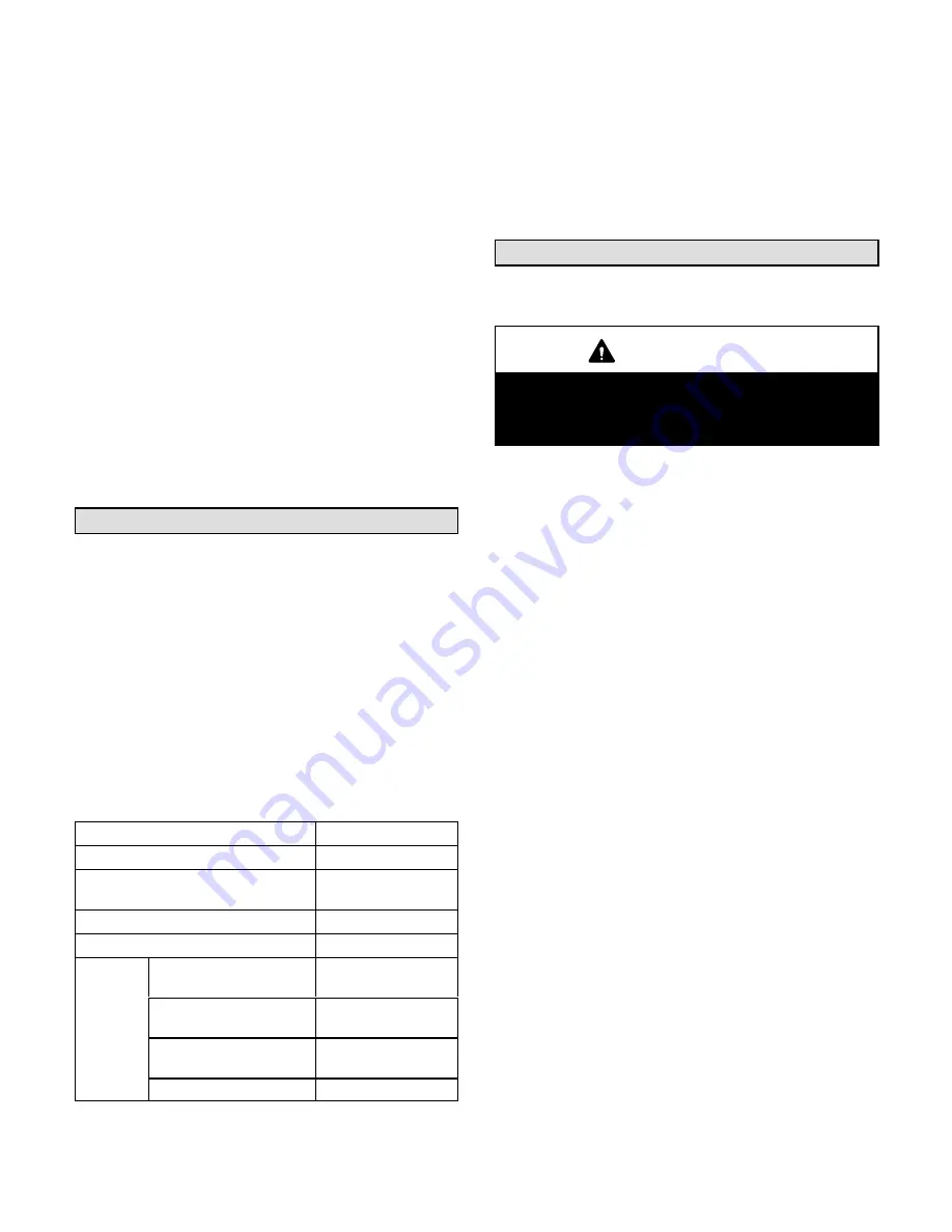
If water impurities exceed the maximum allowable
levels shown in table 19, the potential for serious
corrosion or scaling exists.
TABLE 19
ALLOWABLE WATER QUALITY LEVELS
Condition
Acceptable Level
pH
7 to 9.0
Total Hardness
(Calcium and Magnesium)
Should not exceed
350 ppm
Iron Oxides
Less than 1 ppm
Iron Bacteria
No level allowable
Corrosion
Ammonia, Ammonium
Hydroxide
0.5 ppm maximum
Ammonium chloride,
Ammonium
0.5 ppm maximum
Nitrate Ammonium
Sulfate
0.5 ppm maximum
Hydrogen Sulfide
No level allowable
Maintenance
Water quality should be checked periodically to maintain
acceptable water quality levels. If the water-to-refrigerant
coil becomes contaminated with dirt or scaling, the coil
will have to be back-flushed and cleaned with chemicals
that will remove the scale. This service should be
performed by an experienced water treatment specialist.
Service
The unit should be inspected once a year by a qualified
service technician.
CAUTION
Label all wires prior to disconnection when servic
ing controls. Wiring errors can cause improper and
dangerous operation. Verify proper operation after
servicing.
A-Filters
Units are equipped with the following filters:
036/060 Units: Four 16 X 20 X 2” (406 X 508 X 51mm)
120 Units - Six 16 X 25 X 2” (406 X 635 X 51mm)
240 Units: Twelve 20 X 20 X 2” (508 X 508 X 51mm)
Filters should be checked monthly and replaced when
necessary with filters of like kind and size. Take note of
air flow direction marking on filter frame when
reinstalling filters. See figure 32.
NOTE-Filters must be U.L.C. certified or equivalent for
use in Canada.
Check and replace or clean economizer filters as needed.
B-Lubrication
All motors are lubricated at the factory. No further
lubrication is required.
C-Evaporator Coil
Inspect and clean coil at beginning of each cooling
season. Clean using mild detergent or commercial coil
cleaner. Flush coil and condensate drain with water
taking care not to get insulation, filters and return air
ducts wet.
D-Supply Air Blower Wheel
Annually inspect supply air blower wheel for accumulated
dirt or dust. Turn off power before attempting to remove
access panel or to clean blower wheel.


