


Page 9
I-UNIT COMPONENTS
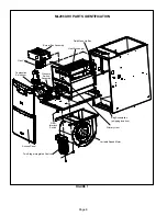
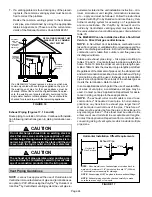
ML296UHV(X) unit components are shown in figure 1. The
gas valve, combustion air inducer and burners can be ac
cessed by removing the access panel. Electrical compo
nents are in the control box (figure 2) found in the blower
section.
CAUTION
Electrostatic discharge can affect elec
tronic components. Take precautions
to neutralize electrostatic charge by
touching your hand and tools to metal
prior to handling the control.
A- Control Box
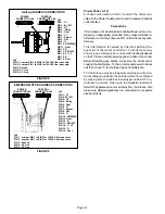
1. Control Transformer (T1)
A transformer located in the control box provides power to
the low voltage section of the unit. Transformers on all
models are rated 40VA with a 120V primary and a 24V sec
ondary.
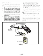
2. Door Interlock Switch (S51)
A door interlock switch rated 14A at 125VAC is wired in se
ries with line voltage. When the inner blower access panel
is removed the unit will shut down.
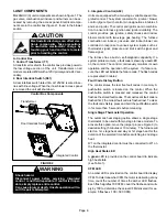
FIGURE 2
Control Box Components
Integrated Control
Door Interlock Switch
Transformer
WARNING
Shock hazard.
Disconnect power before servicing. Integrated
control is not field repairable. If control is inoper
able, simply replace entire control.
Can cause injury or death. Unsafe operation will re
sult if repair is attempted.
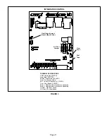
3. Integrated Control (A92)
Units are equipped with a two-stage, variable speed inte
grated control. The system consists of a ignition / blower
control (figure 3) with control pin designations in tables 3
and 4 and ignitor. The control and ignitor work in combina
tion to ensure furnace ignition and ignitor durability. The
control provides gas ignition, safety checks and indoor
blower control with two-stage gas heating. The furnace
combustion air inducer, gas valve and indoor blower are
controlled in response to various system inputs such as
thermostat signal, pressure and limit switch signal and
flame signal.
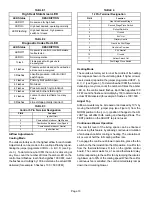
The furnace has a built-in, self-diagnostic capability. If a
system problem occurs, a fault code is shown by a
red
LED
on the control. The control continuously monitors its own
operation and the operation of the system. If a failure oc
curs, the LED will indicate the failure code. The flash codes
are presented in table 2.
Fault Code History Button
The control stores the last five fault codes in memory. A
pushbutton switch is located on the control. When the
pushbutton switch is pressed and released, the control
flashes the stored fault codes. The most recent fault code is
flashed first; the oldest fault code is flashed last. To clear
the fault code history, press and hold the pushbutton switch
in for more than 5 seconds before releasing.
Single Stage Thermostat Operation
The automatic heat staging option allows a single stage
thermostat to be used with two stage furnace models. To
activate this option, move the jumper pin (see Figure 3) to
desired setting (5 minutes or 10 minutes). The furnace will
start on 1st stage heat and stay at 1st stage heat for the
duration of the selected time before switching to 2nd stage
heat.
W1 on the integrated control must be connected to W1 on
the thermostat.
High Heat State LED
A
green
LED is provided on the control board to indicate
high heat state
(see Table 1).
CFM LED
An amber LED is provided on the control board to display
CFM. To determine what CFM the motor is delivering at any
time, count the number of times the amber LED flashes.
Each flash signifies 100 CFM; count the flashes and multi
ply by 100 to determine the actual CFM delivered (for ex
ample: 5 flashes x 100 = 500 CFM).


