


Page 10
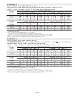
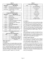
TABLE 1
High Heat State Green LED
LED Status
DESCRIPTION
LED Off
No demand for high heat
LED On
High heat demand, operating normally
LED Flashing
High heat demand, high pressure
switch not closed
TABLE 2
Diagnostic Codes Red LED
LED Status
DESCRIPTION
LED Off
No power to control or control harware
fault detected.
LED On
Normal operation.
1 Flash
Flame present with gas vavle
de-energized.
2 Flashes
Pressure switch closed with combustion
air inducer de-energized.
3 Flashes
Low-fire pressure, rollout or limit
switch open.
4 Flashes
Primary limit switch open.
5 Flashes
Not used
6 Flashes
Pressure switch cycle lockout.
7 Flashes
Lockout, burners fail to light.
8 Flashes
Lockout, buners lost flame too many
times.
9 Flashes
Line voltage polarity incorrect.
TABLE 3
Control 5 Pin Terminal Designation
PIN #
Function
1
Ignitor (Hot)
2
Combustion Air Inducer High Speed
3
Combustion Air Inducer Low Speed
4
Combustion Air Inducer Neutral
5
Ignitor Neutral
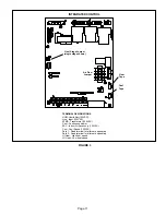
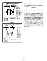
Airflow Adjustments
Cooling Mod
e
The units are factory set for the highest airflow for each model.
Adjustments can be made to the cooling airflow by reposi
tioning the jumper plug marked COOL – A, B, C, D (see Fig
ure 3). To determine what CFM the motor is delivering at
any time, count the number of times the amber LED on the
control board flashes. Each flash signifies 100 CFM; count
the flashes and multiply by 100 to determine the actual CFM
delivered (for example: 5 flashes x 100 = 500 CFM).
TABLE 4
12 Pin Terminal Designation
PIN #
Function
1
Gas Valve Second Stage
2
Second Stage Prove Switch
3
Rollout Switch In
4
Ground
5
24V Hot
6
Primary Limit In
7
Gas Valve First Stage
8
Gas Valve Common
9
24V Neutral
10
Ground
11
Rollout Switch Out
12
First Stage Prove Switch
Heating Mode
These units are factory set to run at the middle of the heating
rise range as shown on the unit rating plate. If higher or lower
rise is desired, reposition the jumper plug marked HEAT - A,
B, C, C (see Figure 3) . To determine what CFM the motor is
delivering at any time, count the number of times the amber
LED on the control board flashes. Each flash signifies 100
CFM; count the flashes and multiply by 100 to determine the
actual CFM delivered (for example: 5 flashes x 100= 500.
Adjust Tap
Airflow amounts may be increased or decreased by 10% by
moving the ADJUST jumper plug (see Figure 3) from the
NORM position to the (+) or (-) position. Changes to the AD
JUST tap will affect both cooling and heating airflows. The
TEST position on the ADJUST tap is not used.
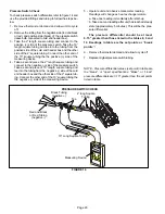
Continuous Blower Operation
The comfort level of the living space can be enhanced
when using this feature by allowing continuous circulation
of air between calls for cooling or heating. The circulation of
air occurs at half the full cooling airflow rate.
To engage the continuous blower operation, place the fan
switch on the thermostat into the ON position. A call for fan
from the thermostat closes R to G on the ignition control
board. The control waits for a 1 second thermostat delay
before responding to the call for fan by ramping the circulat
ing blower up to 50% of the cooling speed. When the call for
continuous fan is satisfied, the control immediately ramps
down the circulating blower.


