


Page 7
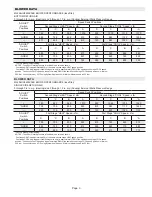
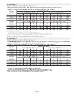
BLOWER DATA
ML296UH110XV60C BLOWER PERFORMANCE (less filter)
BOTTOM RETURN AIR, RETURN AIR FROM BOTH SIDES OR RETURN AIR FROM BOTTOM AND ONE SIDE
0 through 0.8 in. w.g. (Heating) and 0 through 1.0 in. w.g. (Cooling) External Static Pressure Range
“ADJUST”
Switch
Positions
Speed Switch Positions
Second Stage “HEAT” Speed - cfm
Second Stage “COOL” Speed - cfm
D
1
C
B
A
D
C
B
1
A
+
1560
1760
1905
2080
1312
1560
1744
1955
1
NORM
1415
1610
1740
1930
1219
1405
1569
1796
—
1285
1485
1560
1745
1075
1272
1428
1634
“ADJUST”
Switch
Positions
First Stage “HEAT” Speed - cfm
First Stage “COOL” Speed - cfm
D
1
C
B
A
D
C
B
1
A
+
1155
1325
1420
1565
937
1064
1247
1407
1
NORM
1055
1200
1310
1480
864
972
1146
1282
—
935
1075
1170
1315
790
888
1025
1167
1
Factory default jumper setting.
NOTES - The effect of static pressure is included in air volumes shown.
First stage HEAT is approximately
91%
of the same second stage HEAT speed position.
First stage COOL (two-stage air conditioning units only) is approximately
70%
of the same second stage COOL speed
position.
Continuous Fan Only speed is approximately
38
%
of the same second stage COOL speed position - minimum
500 cfm.
Lennox Harmony III™ Zoning System Applications - Minimum blower speed is 478 cfm.
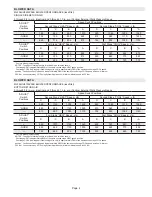
BLOWER DATA
ML296UH110XV60C BLOWER PERFORMANCE (less filter)
SINGLE SIDE RETURN AIR −
Air volumes in
bold
(over 1800 cfm) require Optional Return Air Base and
field fabricated transition
to accommodate 20 x 25 x 1 in. air filter in order to maintain proper air velocity.
0 through 0.8 in. w.g. (Heating) and 0 through 1.0 in. w.g. (Cooling) External Static Pressure Range
“ADJUST”
Switch
Positions
Speed Switch Positions
Second Stage “HEAT” Speed - cfm
Second Stage “COOL” Speed - cfm
D
1
C
B
A
D
C
B
1
A
+
1530
1735
1845
2025
1270
1519
1712
1899
1
NORM
1380
1555
1705
1860
1170
1363
1555
1774
—
1235
1440
1540
1710
1059
1218
1401
1581
“ADJUST”
Switch
Positions
First Stage “HEAT” Speed - cfm
First Stage “COOL” Speed - cfm
D
1
C
B
A
D
C
B
1
A
+
1140
1280
1390
1550
918
1053
1198
1366
1
NORM
1040
1175
1260
1430
820
964
1095
1231
—
910
1080
1150
1265
722
852
987
1116
1
Factory default jumper setting.
NOTES - The effect of static pressure is included in air volumes shown.
First stage HEAT is approximately
91%
of the same second stage HEAT speed position.
First stage COOL (two-stage air conditioning units only) is approximately
70%
of the same second stage COOL speed
position.
Continuous Fan Only speed is approximately
38
%
of the same second stage COOL speed position - minimum
500 cfm.
Lennox Harmony III™ Zoning System Applications - Minimum blower speed is 478 cfm.


