


Page 28
E−Testing Gas Supply Pressure
When testing supply gas pressure, connect test gauge to
inlet pressure tap (field provided). Check gas line pressure
with unit firing at maximum rate or high fire. Low pressure
may result in erratic operation or underfire. High pressure
can result in permanent damage to gas valve or overfire.
For G32 units, operating pressure at unit gas connection
must be between 4.5" W.C. and 13.0" W.C.
On multiple unit installations, each unit should be checked
separately, with and without units operating. Supply pres
sure must fall within range listed in previous paragraph.
F−Check Manifold Pressure
Manifold
Operating
Pressure is the manifold pressure
measured during normal operation (sensing burner box
pressure). Manifold
Absolute
Pressure is the manifold
pressure measured when the gas valve regulator is operat
ing at factory preset level (sensing atmospheric pressure).
After line pressure has been checked and adjusted, check
manifold absolute pressure. Move pressure gauge to outlet
pressure tap located on unit gas valve (GV1). Checks of
manifold absolute pressure are made as verification of proper
regulator adjustment.
Manifold operating pressure for the G32 can be measured at
any time the gas valve is open and is supplying gas to the
unit. For natural gas units, normal manifold operating pres
sure for high fire is 3.5 in. W.C. and 1.7 in. W.C. for low fire.
DO not attempt to adjust WhiteRodgers valve on low fire.
WhiteRodgers valve is not adjustable on low fire
. For
propane units, normal manifold operating pressure for high
fire is 7.5 in. W.C. and 3.5 in. W.C for low fire.
IMPORTANT
For safety, connect a shutoff valve between the
manometer and the gas tap to permit shut off of
gas pressure to the manometer.
The gas valve is factory set and should not require adjust
ment. Also, gas valve regulation varies with burner box
pressure (figure 17).
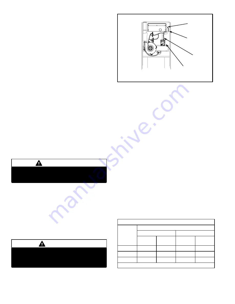
*Manifold Absolute Pressure Measurement and Adjust
ment
1 − Connect test gauge to outlet tap on gas valve.
2 − Disconnect pressure sensing hose from gas valve
and plug hose. Leave hose barb on valve open to at
mosphere. See figure 39.
3 − Start unit on high fire and allow 5 minutes for unit to
reach steady state.
WARNING
Fire and explosion hazard.
These instructions MUST be followed exactly.
Can cause a fire or explosion resulting in property
damage, personal injury or loss of life.
FIGURE 39
LEFT SIDE OF PRESSURE SWITCH = MORE NEGATIVE
RIGHT SIDE OF PRESSURE SWITCH = LESS NEGATIVE
(Closer to Zero)
GAS
VALVE
SENSING
HOSE
BURNER
BOX
SENSING
HOSE
HOSE
BARB
MANIFOLD CHECK
(G32−75 SHOWN)
GAS VALVE
4 − While waiting for the unit to stabilize, notice the flame.
Flame should be stable and should not lift from burner.
Natural gas should burn blue.
5 − After allowing unit to stabilize for 5 minutes, record
manifold pressure. Manifold pressure should read 3.5"
+ or − 0.3" W.C. for natural gas and 7.5" + or − 0.3" W.C.
for propane. Regulator cap must be installed when
reading pressures.
NOTE−Shut unit off and remove manometer as soon as
an accurate reading has been obtained. Take care to re
place pressure tap plug.
NOTE−During this test procedure, the unit will be
overfiring:
Operate unit only long enough to obtain accurate read
ing to prevent overheating heat exchanger.
Attempts to clock gas valve during this procedure will
be inaccurate. Measure gas flow rate only during nor
mal unit operation.
6 − When test is complete remove obstruction from hose
and return hose to gas valve barb.
G− Proper Gas Flow (Approximate)
Furnace should operate at least 5 minutes before check
ing gas flow. Determine time in seconds for
two
revolu
tions of gas through the meter. (Two revolutions assures a
more accurate time.)
Divide by two
and compare to time
in table 14 below. Adjust manifold pressure on gas valve to
match time needed.
NOTE−To obtain accurate reading, shutoff all
other gas appliances connected to meter.
TABLE 14
GAS METER CLOCKING CHART
Seconds for One Revolution
G32 Unit
Natural
LP
G32 Unit
1 cu ft
Dial
2 cu ft
Dial
1 cu ft
Dial
2 cu ft
DIAL
−75
48
96
120
240
−100
36
72
90
180
−125
29
58
72
144
Natural−1000 btu/cu ft LP−2500 btu/cu ft