Lennox G32 SERIES Unit Information Download Page 26

Page 26

III−STARTUP
A−Preliminary and Seasonal Checks

1 − Inspect electrical wiring, both field and factory installed

for loose connections. Tighten as required.

2 − Check voltage at disconnect switch. Voltage must be

within range listed on the nameplate. If not, consult the
power company and have voltage condition corrected
before starting unit.

3 − Inspect condition of condensate traps and drain as

sembly. Disassemble and clean seasonally.

B−Heating StartUp

FOR YOUR SAFETY READ BEFORE LIGHTING

CAUTION

Shock and burn hazard.
G32 units are equipped with the SureLight ignition
system. Do not attempt to light manually.

WARNING

Do not use this furnace if any part has been
underwater. Inspect the furnace and replace any
part of the control system and any gas control
which has been under water.

WARNING

If overheating occurs or if gas supply fails to shut
off, shut off the manual gas valve to the appliance
before shutting off electrical supply.

CAUTION

Before attempting to perform any service or main
tenance, turn the electrical power to unit OFF at
disconnect switch.

BEFORE LIGHTING smell all around the appliance area
for gas. Be sure to smell next to the floor because some gas
is heavier than air and will settle on the floor.

Use only your hand to turn the gas control switch. Never
use tools. If the switch will not turn by hand, do not try to re
pair it, call a qualified service technician. Force or at
tempted repair may result in a fire or explosion.

G32 units are equipped with the SureLight ignition system. DO
NOT attempt to manually light burners on this furnace. Each
time thermostat calls for heat, burners will be automatically lit.
The ignitor does not get hot when there is no call for heat on
units with SureLight ignition system.

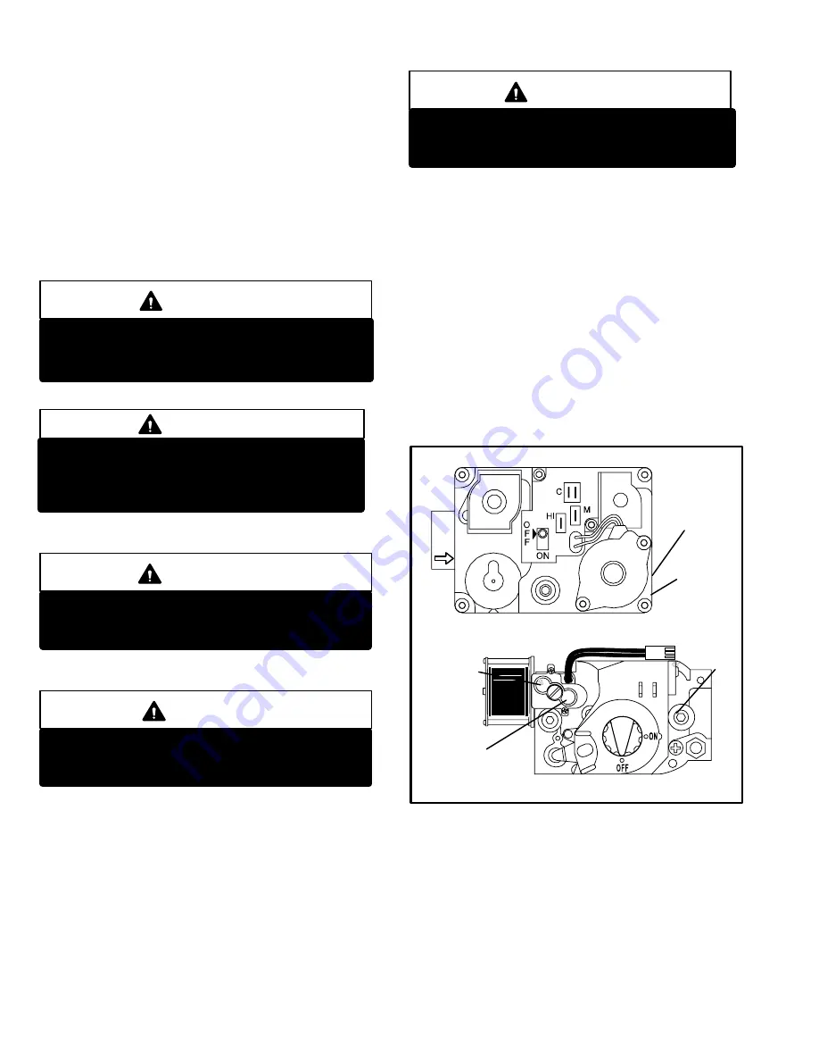
How To Operate Gas Valve (Figure 

37

)

WARNING

If you do not follow these instructions exactly, a
fire or explosion may result causing property
damage, personal injury or loss of life.

 1 −

STOP

! Read the safety information at the beginning of

this section.

 2 − Set thermostat to lowest setting.

 3 − Turn off all electrical power to furnace.

 4 − This appliance is equipped with an ignition device

which automatically lights the burner. Do 

not

 try to

light the burner by hand.

 5 − Remove unit access panel.

 6 −

White Rodgers 36E Gas Valve, 

switch lever to 

OFF

.

Do not force. See figure 37.

 7 − Wait five (5) minutes to clear out any gas. If you then

smell gas,

 STOP

! Immediately call your gas supplier from

a neighbor’s phone. Follow the gas supplier’s instruc
tions. If you do not smell gas go to next step.

WHITE RODGERS 36E SERIES GAS VALVE

FIGURE 37

HIGH HEAT

MANIFOLD

PRESSURE

ADJUSTMENT

ON SIDE

(under cap)

MANIFOLD

PRESSURE

OUTLET

HONEYWELL VR8205 SERIES Gas Valve

BOTH VALVES SHOWN IN OFF POSITION

HIGH HEAT

MANIFOLD

PRESSURE

ADJUSTMENT

(under cap)

MANIFOLD

PRESSURE

OUTLET ON

SIDE

LOW HEAT
MANIFOLD

PRESSURE

ADJUSTMENT

(under cap)

 8 −

White Rodgers 36E Gas Valve, 

switch lever to 

ON

. Do

not force.

 9 − Replace access panel.

10− Turn on all electrical power to unit.

11− Set thermostat to desired setting.

12− If the appliance will not operate, follow the instructions

To Turn Off Gas To Unit" and call your service techni
cian or gas supplier.

Turning Off Gas To Unit

 1 − Set thermostat to lowest setting.

Summary of Contents for G32 SERIES

Page 1: ...Information contained in this manual is intended for use by qualified service technicians only All specifications are subject to change Procedures outlined in this manual are presented as a recommenda...

Page 2: ...s kg 1 package 157 71 186 84 198 90 218 99 Electrical characteristics 120 volts 60 hertz 1 phase all models less than 12 amps OPTIONAL ACCESSORIES Must Be Ordered Extra Concentric Vent Intake Air Roof...

Page 3: ...c Blower Taps External Static Pressure High Medium High Medium Medium Low Low in w g Pa cfm L s Watts cfm L s Watts cfm L s Watts cfm L s Watts cfm L s Watts 0 0 2400 1135 1255 2185 1030 1070 1940 915...

Page 4: ...s in mm in mm in mm 15 4 6 2 51 2 51 2 51 20 6 1 2 51 2 51 3 76 25 7 6 2 51 2 51 3 76 30 9 1 2 51 3 51 3 76 40 12 2 2 51 3 51 3 76 50 15 2 2 51 3 51 3 76 55 16 8 2 51 3 76 3 76 60 18 3 3 76 3 76 3 76...

Page 5: ...HEAT EXCHANGER ASSEMBLY CONDENSER COIL CONTROL TRANSFORMER CONTROL VOLTAGE CIRCUIT BREAKER WARM HEADER COLLECTOR BOX COLD HEADER COLLECTOR BOX TWO SPEED COMBUSTION AIR INDUCER COMBUSTION AIR ORIFICE...

Page 6: ...tom return or cut out side return as required for return air duct connec tion A Make Up Box Figure 3 The line voltage make up box is shown in figure 3 The box may be installed inside or outside the un...

Page 7: ...mbly for flame viewing Always operate the unit with the burner box cover in place Burn ers can be removed as an assembly for service Burner main tenance and service is detailed in the MAINTENANCE sec...

Page 8: ...it open Units with board 63K8901 or 24L85 Limit must close within 5 trials for ignition or board goes into one hour limit Watchguard Units with board 56L83 or 97L48 Limit must close within 3 minutes o...

Page 9: ...After the 15 second pre purge period the SureLight ignitor warms up for 20 seconds after which the gas valve opens for a 4 second trial for ignition G32 units with board 63K89 24L85 or 56L83 the ignit...

Page 10: ...tion board The board can be uti lized in three modes with a SINGLE STAGE thermostat a TWO STAGE thermostat or with a second stage high fire delay called W2 TIMED The two stage board is equipped with a...

Page 11: ...a successful ignition the SureLight control utilizes less power to energize the ignitor on successive calls for heat The control continues to ramp down the voltage to the ignitor until it finds the l...

Page 12: ...ter the cool demand has been satisfied can be adjusted by flipping dip switch 4 The unit is shipped with a factory fan off setting of 45 seconds Fan off time will affect comfort and is adjustable to s...

Page 13: ...Low Cool and Continuous Fan Speed TABLE 8 Integrated Control Board 5 Pin Terminal PIN Function 1 Ignitor 2 Combustion Air Inducer High Speed 3 Combustion Air Inducer Low Speed 4 Combustion Air Inducer...

Page 14: ...urners failed to ignite OR limit open more than 3 minutes OR lost flame sense 5 times in one heating cycle OR pressure switch opened 5 times in one heating cycle SLOW FLASH OFF Flame sensed without ga...

Page 15: ...temperature limit located on the right side of the burner box assembly see figure 16 S47 is wired to the burner ignition control A92 When S47 senses flame rollout indicating a blockage in the combust...

Page 16: ...box Both switches are a single pole single throw normally open pressure switch electrically connected in series with the igni tion control The purpose of the switch is to prevent burner operation if...

Page 17: ...s are farther from zero figure 19 the unit may have a restricted flue inlet or other problem Measuring pressure differential The differential pressure is the difference in pressure mea sured on either...

Page 18: ...end of pipe NOTE Time is critical at this stage Do not allow primer to dry before applying cement 7 Immediately after applying last coat of cement to pipe and while both inside socket surface and end...

Page 19: ...ould cause an unsafe condition 3 Insofar as is practical close all building doors and win dows and all doors between the space in which the ap pliances remaining connected to the common venting system...

Page 20: ...f exhaust pipe must be painted or wrapped to protect insula tion from deterioration NOTE During extremely cold temperatures below approximately 20 F 6 67 C units with long runs of vent pipe through un...

Page 21: ...CUMULATION UNCONDITIONED SPACE 12 305 MIN for 2 51 20 508 MAX for 3 76 8 203 MIN 1 2 13 FOAM INSULATION 1 2 13 FOAM INSULATION IN UNCONDITIONED SPACE PROVIDE SUPPORT FOR INTAKE AND EXHAUST LINES EVERY...

Page 22: ...2 x 1 1 2 51 x 38 REDUCER BUSHING LOCATION FOR OFFSET TERMINATION Optional Turndown Not Shown May Be Used on Intake Only FIGURE 28 METAL OR PLASTIC STRAPPING OR LARGE WIRE TIES 10 Suspend piping using...

Page 23: ...TAKE VENT GRADE GRADE EXHAUST VENT INTAKE VENT 34 864 12 305 9 229 NOTE Enclosed exhaust pipe is insulated with 1 2 13mm foam insulation If intake and exhaust pipes are reversed slit and remove foam i...

Page 24: ...nent manner and must be water tight Teflon tape is recommended to seal the joint For Right Hand Side Condensate Exit Install the nipple adapter assembly from the outside of the cabinet and insert the...

Page 25: ...own the walls of the flue pipe and into drain hose 5 Water drains down through the flue drain hose and is emptied into the header box con densate trap 6 When the cold header box condensate trap is ful...

Page 26: ...ition system DO NOT attempt to manually light burners on this furnace Each time thermostat calls for heat burners will be automatically lit The ignitor does not get hot when there is no call for heat...

Page 27: ...CO One method for testing the CO2 CO content is the Bachar ach CO2 test with the Fyrite CO2 indicator Other methods of testing CO2 CO are available Closely follow the instruc tions included in the te...

Page 28: ...test gauge to outlet tap on gas valve 2 Disconnect pressure sensing hose from gas valve and plug hose Leave hose barb on valve open to at mosphere See figure 39 3 Start unit on high fire and allow 5 m...

Page 29: ...within the range of AIR TEMP RISE F listed on the unit rating plate To Measure Temperature Rise 1 Place plenum thermometers in the supply and return air plenums Locate supply air thermometer in the fi...

Page 30: ...rd See figure 8 Unused taps must be secured on dummy terminals PARK M1 and or PARK M2 on the SureLight board The heating tap is connected to the ACB HEAT terminal and the cooling tap is connected to t...

Page 31: ...standard right hand threads 14 Disconnect the drain hose from the flue transition to the elbow on the cold header collector box trap 15 Disconnect the 3 pin plug from the combustion air blower at the...

Page 32: ...rom installation manu al light and run unit for 5 minutes to ensure heat ex changer is clean dry and operating safely Cleaning the Burner Assembly NOTE Surgical mask and safety glasses should be worn...

Page 33: ...are tight to ensure a leak tight burn er box Tighten the two screws underneath the box Again inspect the grommet to ensure a tight seal 19 Tighten the two screws holding the manifold bracket to the ve...

Page 34: ...IRE IN J69 G C R Y FLAME ROLLOUT SWITCH W2 W1 W2 TWO STAGE RELAY CONTROL PIGTAIL FURNACE MAY BE CONTROLLED BY EITHER A SINGLE OR TWO STAGE THERMOSTAT TWO STAGE THERMOSTAT SHOWN FUSED DISCONNECT OR CIR...

Page 35: ...Page 35 G32 2 UNIT DIAGRAM...

Page 36: ...Page 36 G32 3 UNIT DIAGRAM...

Page 37: ...gizes combustion air blower B6 on low speed Combustion air blower runs until com bustion air blower switch S102 or S128 onG32 75 units closes switch will close within 2 1 2 minutes or control goes int...

Page 38: ...VE OFF COMBUSTION AIR INDUCER ON INDOOR BLOWER ON LED 1 SLOW FLASH LED 2 OFF GAS VALVE OFF COMBUSTION AIR INDUCER OFF INDOOR BLOWER OFF DELAY LED 1 OFF LED 2 SLOW FLASH Sequence holds until pressure s...

Page 39: ...TAGE HEAT FLAME PRESENT Continuous flame check FLAME SIGNAL u0 60 microamps PRIMARY LIMIT SWITCH CLOSED ROLLOUT SWITCH CLOSED PRESSURE SWITCH CLOSED CONTINUED ON NEXT PAGE CONTROL CHECKS RETRY FOR IGN...

Page 40: ...SSURE SWITCH CLOSED HIGH HEAT GAS VALVE OPEN 8 SEC DELAY GAS VALVE DE ENERGIZED INDOOR BLOWER DE ENERGIZED COMBUSTION AIR INDUCER ON FOR 2 5 MINUTES NO PRESSURE SWITCH CLOSED PRESSURE SWITCH WATCHGUAR...

Page 41: ...UNCHANGED THROUGHOUT COOLING CYCLE THERMOSTAT CALLS FOR COOLING COMPRESSOR CONTACTOR AND SYSTEM FAN ENERGIZED WITH 0 SECOND DELAY COOLING SPEED ACC TERM ENERGIZED COMPRESSOR OFF THERMOSTAT OPENS SYST...

Page 42: ...Y THERMOSTAT OPENS COMBUSTION AIR AND HTG ACC TERMINAL DE ENERGIZE SYSTEM FAN SWITCHED TO ACB COOL SPEED ACC TERM REMAINS ON THERMOSTAT OPENS BOARD 63K89 SYSTEM FAN OFF ACC TERM OFF AFTER OFF DELAY CO...

Page 43: ...Page 43 TYPICAL G32 5 6 SCHEMATIC WIRING DIAGRAM...

Page 44: ...ve remains on first stage heat ignitor de energizes 8 After 45 second delay indoor blower B3 is energized on low heat speed The furnace will stay in this mode until first stage de mand is satisfied OR...

Page 45: ...DS 1 SIMULTANEOUS FAST FLASH DS 2 SIMULTANEOUS FAST FLASH YES PRIMARYLIMIT SWITCH CLOSED YES NO COMBUSTION AIR INDUCER OFF INDOOR BLOWER ON HAS PRIMARY LIMIT RESET WITHIN 3 MINUTES DS1 SLOW FLASH DS2...

Page 46: ...EPLACED OR RECONNECTED DS1 AND DS2 ALTERNATING FAST FLASH YES AT END OF IGNITOR 20 SECOND WARM UP PERIOD 4 SECOND TRIAL FOR IGNITION GAS VALVE OPENS IGNITOR ENERGIZED DURING 4 SECOND TRIAL UNTIL FLAME...

Page 47: ...LAY DS1 OFF DS 2 SLOW FLASH NO YES C FIRST STAGE HEAT DEMAND SATISFIED DS1 AND DS2 SIMULTANEOUS SLOW FLASH GAS VALVE OFF COMBUSTION AIR INDUCER OFF FOLLOWING POST PURGE INDOOR BLOWER OFF WITH DELAY DS...

Page 48: ...ED BEFORE RETRY WERE 5 ATTEMPTS MADE FOR SECOND STAGE HEAT YES NO SEE BOX C FIRST STAGE HEAT DEMAND SATISFIED HEAT DEMAND SATISFIED DS1 AND DS2 SIMULTANEOUS FAST FLASH YES TWO STAGE THERMOSTAT MODE E2...

Page 49: ...HOLDS UNTIL VOLTAGE RISES ABOVE 75 VOLTS NO YES NO SIGNAL IMPROPER GROUND AT DS SIGNAL HOLDS UNTIL UNIT IS PROPERLY GROUNDED INDOOR BLOWER ENERGIZED ON FIRST STAGE COOL SPEED AFTER 2 SECOND DELAY FIR...

Page 50: ...ED YES NO THERMOSTAT CALLS FOR SECOND STAGE HEAT YES INDOOR BLOWER SWITCHES TO HIGH HEAT SPEED AFTER 30 SECOND RECOGNITION PERIOD SECOND STAGE HEAT DEMAND SATISFIED YES YES INDOOR BLOWER RAMPS DOWN TO...

Page 51: ...t 1 2 1 Roll out switch open ACTION 1 Manually reset the roll out switch by pushing the top button ACTION 2 Determine the cause of the roll out switch activation before leaving furnace Diagnostic ligh...

Page 52: ...n air blower will cycle 5 seconds on 55 seconds off LED 1 Alternating Fast Flash LED 2 Alternating Fast Flash 2 1 2 Broken or failed ignitor ACTION 1 Unplug ignitor and read resistance across ignitor...

Page 53: ...itch failure code 2 5 minutes after heating demand 4 1 2 Pressure switch does not close due to obstructions in the pressure tubing ACTION 1 Remove any obstructions from the pressure tubing and or taps...

Page 54: ...ts off prior to satisfying T stat demand Diagnostic lights flash the pressure switch code 6 1 2 Condensate drain line is not draining properly ACTION 1 Check condensate line for proper vent slope and...

Page 55: ...ge if possible high tem perature silicon is recommended replace heat exchanger if necessary tag and return heat ex changer to proper Lennox personnel 6 3 4 Insufficient flow through the heat ex change...

Page 56: ...CONTROL SIGNALS LOW FLAME SENSE DURING HEATING MODE Condition Possible Cause Corrective Action Comments 7 0 Unit operates correctly but the diag nostic lights flash low flame sense code 7 1 1 Sense ro...

Reviews: