Page 18
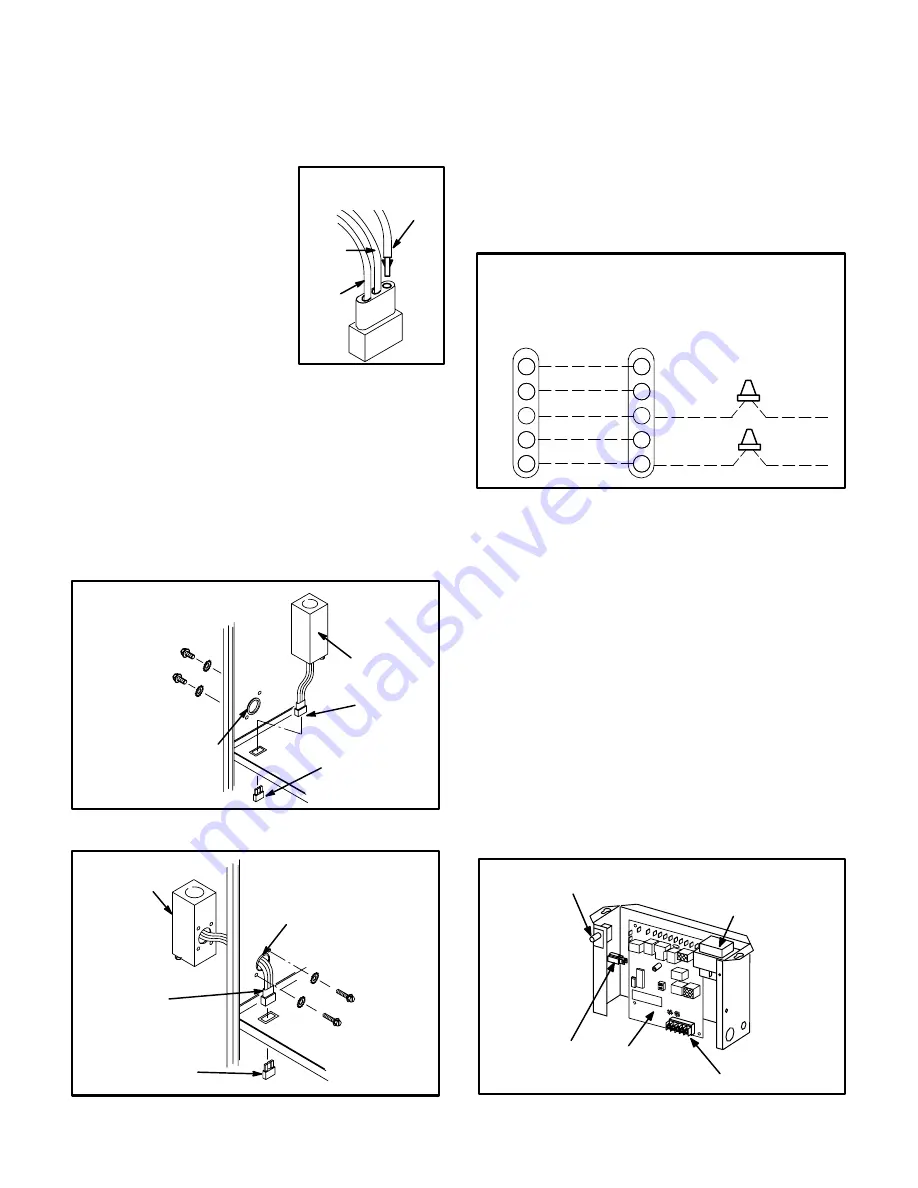
4 - An optional 120 volt accessory wire is provided with
G23(X) units. Install brown accessory wire into J69
jack plug by inserting the pin of the brown wire into the
open socket of the jack. See figure 16. Any accessory
rated up to 4 amps can be
connected to this wire. Con
nect the neutral leg of the ac
cessory to the neutral white
wire in the makeup box.
Connect the brown wire to the
ACC terminal; the terminal is
energized whenever the
blower is energized. You can
also connect the brown wire
to the HTG ACC terminal; the
terminal is energized when
the thermostat calls for heat.
The accessory terminal is energized whenever the
blower is in operation. A troubleshooting flowchart
for the SureLight control is located on pages 28-31.
5 - Insert the three pin (P69) plug from control box into
knockout provided in blower deck.
6 - Connect jack (J69) from makeup box to jack plug in
blower deck.
FIGURE 17
INTERIOR MAKE-UP BOX
INSTALLATION
P69 from
Control Box
J69
MAKE-UP
BOX
BUSHING
FIGURE 18
EXTERIOR MAKE-UP BOX
INSTALLATION
P69 from
Control Box
J69
(Shown with accessory
wire connected)
MAKE-UP
BOX
BUSHING
RING
7 - Select wire size according to the blower motor amps.
8 - Snaphole bushing is provided for the wiring entry
hole in the cabinet. A snaphole plug is provided to
seal the unused wire entry hole.
9 - Install room thermostat according to instructions pro
vided with thermostat. See figure 19 for thermostat
designations. If furnace is being used with heat pump
refer to FM21 installation instruction.
Thermostat
FIGURE 19
COMPRESSOR
COMMON
HS UNIT
COMMON
HS UNIT
COMPRESSOR
G23(X)
Furnace
Condensing
Unit
G23(X) and CONDENSING UNIT
THERMOSTAT DESIGNATIONS
(Refer to specific thermostat and outdoor unit.)
COMMON
POWER
HEAT
INDOOR BLOWER
Y
C
R
W1
G
C
R
W1
G
Y
C
R
G
C
R
W
G
COOLING
10 - Install a separate fused disconnect switch near the
unit so power can be turned off for servicing.
11 - To complete the wiring connections to the equip
ment, refer to the wiring diagrams provided with the
unit. (Figures 22 and 23) Use 18 gauge wire or larger
for thermostat connections.
Indoor Blower Speeds (Refer to Figure 22)
1 - When the thermostat is set to "FAN ON", the indoor
blower will run continuously on low speed when there
is no cooling or heating demand.
2 - When there is a cooling demand, the indoor blower
will run on the cooling speed.
3 - When there is a heating demand, the indoor blower
will run on the heating speed.
G23(X) CONTROL BOX
TRANSFORMER
SureLight
LOW VOLTAGE
TERMINAL STRIP
CIRCUIT
BREAKER
DOOR INTERLOCK SWITCH
FIGURE 20
BLACK
WHITE
NEUTRAL
BROWN
J69
INSTALLING BROWN
ACCESSORY WIRE TO
J69
FIGURE 16


