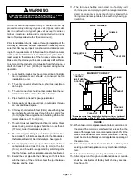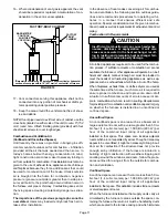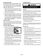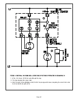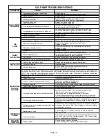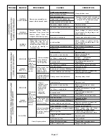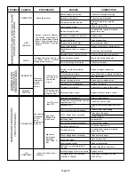
FIGURE 26
STATIC PRESSURE
TEST
MANOMETER
OIL UNIT
Page 19
B-Temperature Rise
Temperature rise for O24 and OF24 units depends on unit in
put, blower speed, blower horsepower and static pressure.
The blower speed must be set for unit operation within the
range of AIR TEMP. RISE
°
F" listed on the unit rating plate.
To Measure Temperature Rise:
1 - Place plenum thermometers in the supply and return air
plenums. Locate supply air thermometer in the first hori
zontal run of the plenum where it will not pick up radiant
heat from the heat exchanger.
2 - Set thermostat to highest setting.
3 - After plenum thermometers have reached their
highest and steadiest readings, subtract the two
readings. The difference should be in the range listed
on the unit rating plate. If the temperature is too low, de
crease blower speed. If temperature is too high increase
blower speed to reduce temperature. To change blower
speed see Blower Speed section.
C-Blower Speed
Blower speed is regulated by means of an adjustable motor
pulley. Open pulley to decrease speed and close pulley to
increase speed. Adjust belt tension as loose as possible
without allowing slippage.
D-External Static Pressure
1 - Measure tap locations as shown in figure 26.
2 - Punch a 1/4" (6 mm) diame
ter hole in supply and return
air plenums. Insert manom
eter hose flush with inside
edge of hole or insulation.
Seal around the hose with
permagum. Connect the
zero end of the manometer
to the discharge (supply) side of the system. On
ducted systems, connect the other end of manometer
to the return duct as above. For systems with non-
ducted returns, leave the other end of the manometer
open to the atmosphere.
3 - With only the blower motor running and the evapora
tor coil dry, observe the manometer reading. Adjust
blower motor speed to deliver the air desired accord
ing to the job requirements.
4 - Pressure drop must not exceed 0.5" W.C. (124.3 Pa).
5 - Seal around the hole when the check is complete.
VII-MAINTENANCE
CAUTION
Never operate unit with access panels to the
blower compartment off or partially open.
A-Filters
If throwaway type filters are used, check monthly and re
place when necessary to assure proper furnace opera
tion. Replace filters with like kind and size.
If reusable type filters are used, check monthly and clean with
water and mild detergent when necessary. When dry, they
should be sprayed with filter handicoater prior to reinstallation.
Filter handicoater is RP Products coating no. 418 and is avail
able as Lennox part no. P85069.
B-Cleaning Heat Exchanger
NOTE-Use papers or protective covering in front of fur
nace while cleaning furnace.
Cleaning the heat exchanger is made easier with a heat ex
changer cleanout kit ABRSH380 (catalog # 35K09) avail
able from Lennox.
Heat Exchanger
1 - Remove vent pipe from furnace.
2 - Remove locking screws and caps from cleanout tubes.
Remove vent access elbow.
3 - Using a long spiral wire brush, sweep down the outer
drum of the heat exchanger. Then using the hose at
tachment, vacuum out loose debris.
4 - Remove locking screw and cap from the observation tube
and with the spiral wire brush, reach upward toward
the rear of the heat exchanger to clean out the cross
over tube.
NOTE- Do not attempt to clean the combustion chamber.
It can be easily damaged.
5 - Replace the cleanout caps and vent access elbow.
Make sure locking screws are secure.
6 - Brush out and vacuum the vent outlet area of the outer
drum and replace vent pipe.
7 - Clean around the burner, blower deck and vestibule area.

